DTC B210D: Battery Voltage Low
DTC B210E: Battery Voltage High
DTC B210E: Battery Voltage High
| caution | If DTC B210D, B210E is set in the occupant classification-ECU, always diagnose the CAN main bus lines. |
TROUBLE JUDGMENT
The occupant classification-ECU sets DTC B210D if the power supply fuse voltage decreases to the specified value or less, and sets DTC B210E if the power supply fuse voltage increases to the specified value or more.
TECHNICAL DESCRIPTION (COMMENT)
The power supply fuse or the occupant classification-ECU may have a problem.
TROUBLESHOOTING HINTS
- The power supply fuse may be defective.
- The occupant classification-ECU may be defective.
- The battery may be defective.
- The wiring harness or connectors may have loose, corroded, or damaged terminals, or terminals pushed back in the connector
DIAGNOSIS
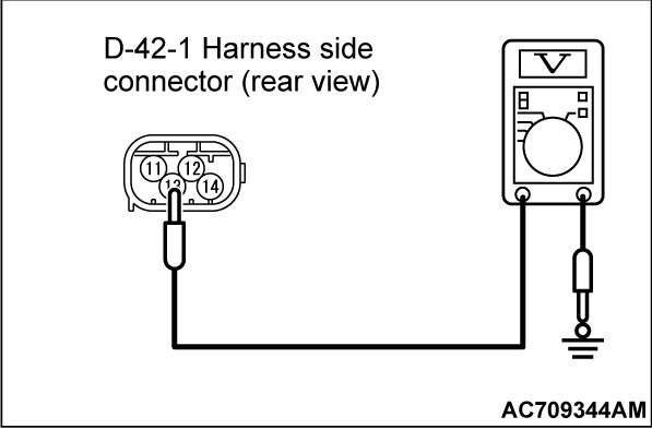
STEP 1. Measure the voltage at the occupant classification-ECU connector.
(1) Disconnect the occupant classification-ECU connector.
(2) Turn the ignition switch to the "ON" position.
(3) Measure the voltage between the occupant classification-ECU connector harness side connector terminal No. 13 and the body ground.
- The voltage should measure 12 volts (battery positive voltage).
Is the measured voltage approximately 12 volts (battery positive voltage)?
STEP 3. Check of short to power supply, short to ground, and open circuit in BTT line between junction block connector and the occupant classification-ECU connector.
Is the check result normal?
 Replace the power supply fuse.
 Repair the wiring harness. And then replace the power supply fuse.
STEP 4. Battery check.
Refer to GROUP 54A, Battery Test  .
. Charge (B210D only) or replace the battery.
 .
.Is the check result normal?
 Charge (B210D only) or replace the battery.
STEP 5. Using scan tool (M.U.T.-III), diagnose the CAN bus line.
| caution | To prevent damage to scan tool (M.U.T.-III), always turn the ignition switch to the "LOCK" (OFF) position before connecting or disconnecting scan tool (M.U.T.-III). |
(2) Turn the ignition switch to the "ON" position.
(3) Diagnose the CAN bus line.
(4) Turn the ignition switch to the "LOCK" (OFF) position.
Is the CAN bus line found to be normal?
STEP 6. Recheck for diagnostic trouble code.
Check again if the DTC is set.
(1) Erase the DTC.
(2) Turn the ignition switch to "ON" position.
(3) Check if the DTC is set.
(4) Turn the ignition switch to the "LOCK" (OFF) position.
Is the DTC set?
STEP 7. Recheck for diagnostic trouble code.
Check again if the DTC is set.
(1) Erase the DTC.
(2) Turn the ignition switch to the "ON" position.
(3) Check if the DTC is set.
(4) Turn the ignition switch to the "LOCK" (OFF) position.
Is DTC B210D or B210E set?
![[Previous]](../../../buttons/fprev.png)
![[Next]](../../../buttons/fnext.png)
