CVT BELT INSPECTION
Required Special Tools:
- MQ600069: Bore scope
JUDGMENT CRITERIA
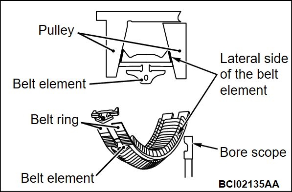
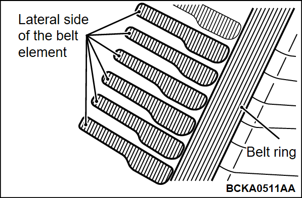
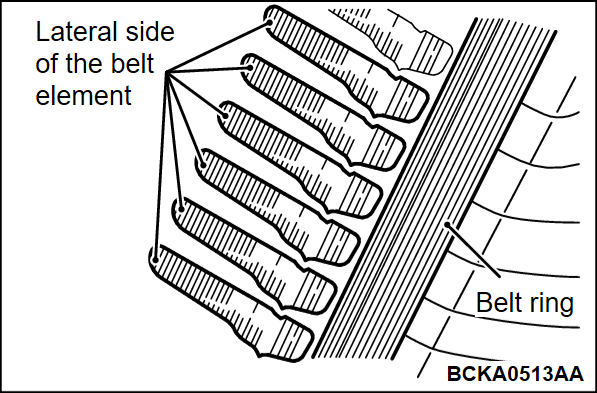
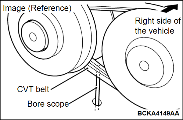
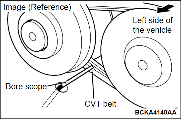
Use special tool bore scope (MQ600069), confirm thatthe lateral side of the belt element illustrated in thefigure is not damaged.
<Good>
The CVT belt is good if the lateral side of the belt element is not damaged, and the lines are regular.
Advance Preparations
1. Bring the selector lever to "N".
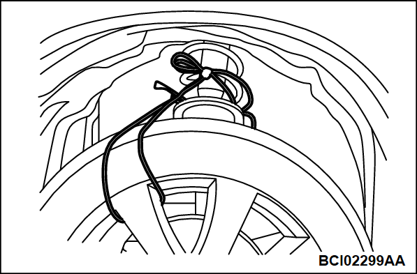
2. Tie the front tire (RH) with a rope, etc. so that the tire does not move.
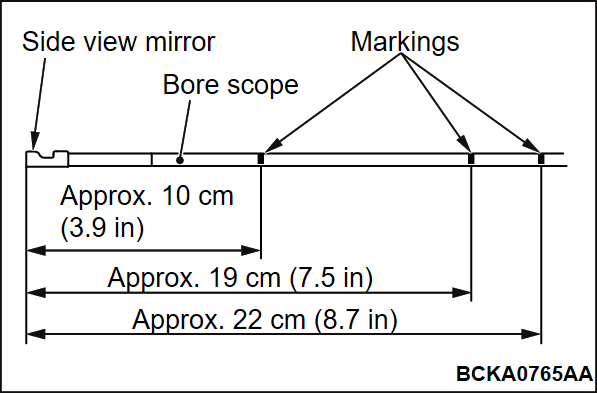
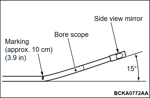
3. Install the side view mirror that is included with the special tool bore scope (MQ600069) on to the bore scope and make 3 markings as indicated in the figure.
| note |
|
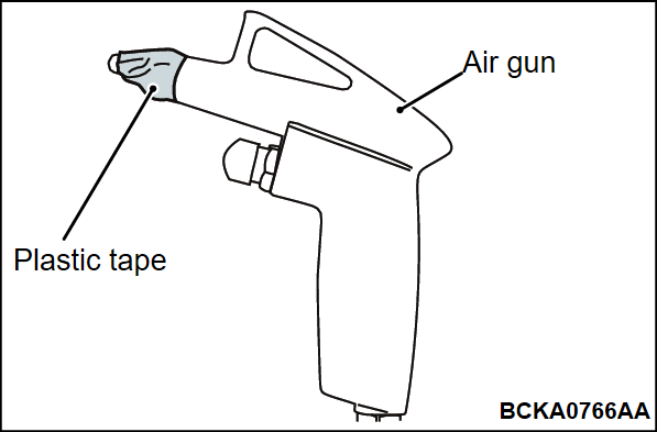
4. Wrap plastic tape around the tip of the air gun approximately 5 times.
| note | The plastic tape is not required if a tapered rubber attachment is used. |
5. Make a marking on the lateral side of the front tire (LH).
Inspection Procedure
| caution | Make sure no foreign material (trash, debris, etc.) enters the transaxle assembly, as this could cause malfunction. |
1. Remove the valve body assembly. While removing the oil pan, if there are bearing fragments, solid metal pieces, etc. on the oil pan, replace the transaxle assembly without inspecting the CVT belt.
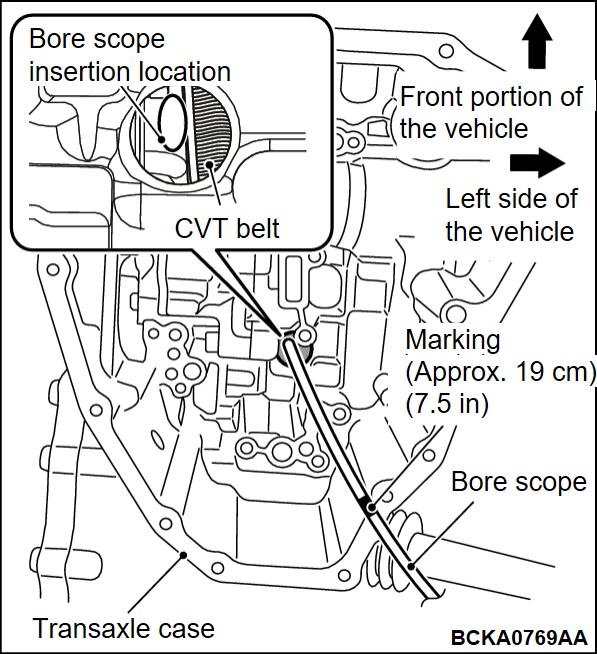
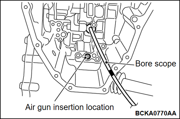
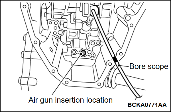
2. Let the side view mirror of the special tool bore scope (MQ600069) face the left side of the vehicle, and insert the scope from the location illustrated in the figure all the way until the end of the transmission case and the marking {approximately 19 cm (7.5 inches)} coincide.
3. Slightly adjust the position of the side view mirror of the special tool bore scope (MQ600069) so that the lateral side of the belt element (right side of the vehicle) is reflected in it.
4. Insert the tip of the air gun at the location illustrated in the figure and press it firmly.
5.
| caution |
|
Slowly continue applying air pressure using the air gun to engage the clutch.
| note | When the front tire (LH) is rotated in the forward direction (rolling direction), as the CVT belt rotates, the clutch gets engaged. |
6.
| caution | If the tire is rotated in the reverse direction (backward direction), the tip of the special tool bore scope (MQ600069) could get caught between the belt and the pulley. Hence rotate the tire in the forward direction. |
Slowly move the front tire (LH) to make 1 rotation while referring to the markings made on the tire during advance preparations and check the entire perimeter of the CVT belt based on the judgment criteria.
| note | If the belt does not move, make sure the air gun is firmly pressed. |
7. If the lateral side of the belt element (right side of the vehicle) is damaged, replace the transaxle assembly. If it is not damaged, proceed to the next step and inspect the other lateral side of the belt element (left side of the vehicle).
8. Use special tool bore scope (MQ600069) at the marked location {approximately 10 cm (3.9 inches)} as illustrated in the figure.
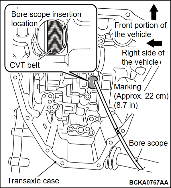
9. Let the side view mirror of the special tool bore scope (MQ600069) face the right side of the vehicle, and insert the scope from the location illustrated in the figure all the way until the end of the transmission case and the marking {approximately 22 cm (8.7 inches)} coincide.
10. Slightly adjust the position of the side view mirror of the special tool bore scope (MQ600069) so that the lateral side of the belt element (left side of the vehicle) is reflected in it.
11. Insert the tip of the air gun at the location illustrated in the figure and press it firmly.
12.
| caution |
|
Slowly continue applying air pressure using the air gun to engage the clutch.
| note | When the front tire (LH) is rotated in the forward direction (rolling direction), as the CVT belt rotates, the clutch gets engaged. |
13.
| caution | If the tire is rotated in the reverse direction (backward direction), the tip of the special tool bore scope (MQ600069) could get caught between the belt and the pulley. Hence rotate the tire in the forward direction. |
Slowly move the front tire (LH) to make 1 rotation while referring to the markings made on the tire during advance preparations and check the entire perimeter of the CVT belt based on the judgment criteria.
| note | If the belt does not move, make sure the air gun is firmly pressed. |
14. If the lateral side of the belt element (left side of the vehicle) is damaged, replace the transaxle assembly. If it is not damaged, proceed to the next step.
15. After the inspection, if some of the adhesive of the plastic tape still remains on the location where the air gun is inserted, remove it with Mitsubishi Motors Genuine parts cleaner (MZ100387) or an equivalent product.
16. Install the valve body assembly.
| note | Replace the valve body assembly if the CVT belt is inspected in the process of troubleshooting (No. P0746, P0796, P0841, P2857, P2858, P2859, P285A). |
![[Previous]](../../../buttons/fprev.png)
![[Next]](../../../buttons/fnext.png)
