[Previous][Next]
REMOVAL AND INSTALLATION
 
 
caution
  • Do not replace the ECM and ETACS-ECU (immobilizer-ECU) simultaneously. Always replace the ECU by ones when the multiple ECU is replaced, and then replace the next ECU after registering the necessary IDs.
  • If the ECM is replaced, perform the coding for it.
  • If the ECM is replaced, use scan tool (M.U.T.-III) to write the VIN (Refer to GROUP 00 - How to Perform Vehicle Identification Number Writing ).
  • After the ECM replacement, idling speed may be unstable because the MFI engine learning is not completed. To make it stable, let the system learn the idling (Refer to GROUP 00 - Precautions before Service, Learning Procedure for Idling in MFI Engine ).
Pre-removal operation
  • Instrument Panel Lower Assembly Removal (Refer to GROUP 52A - Instrument Lower Panel ).
Post-installation operation
  • Instrument Panel Lower Assembly Installation (Refer to GROUP 52A - Instrument Lower Panel ).
<Except vehicles for Canada>
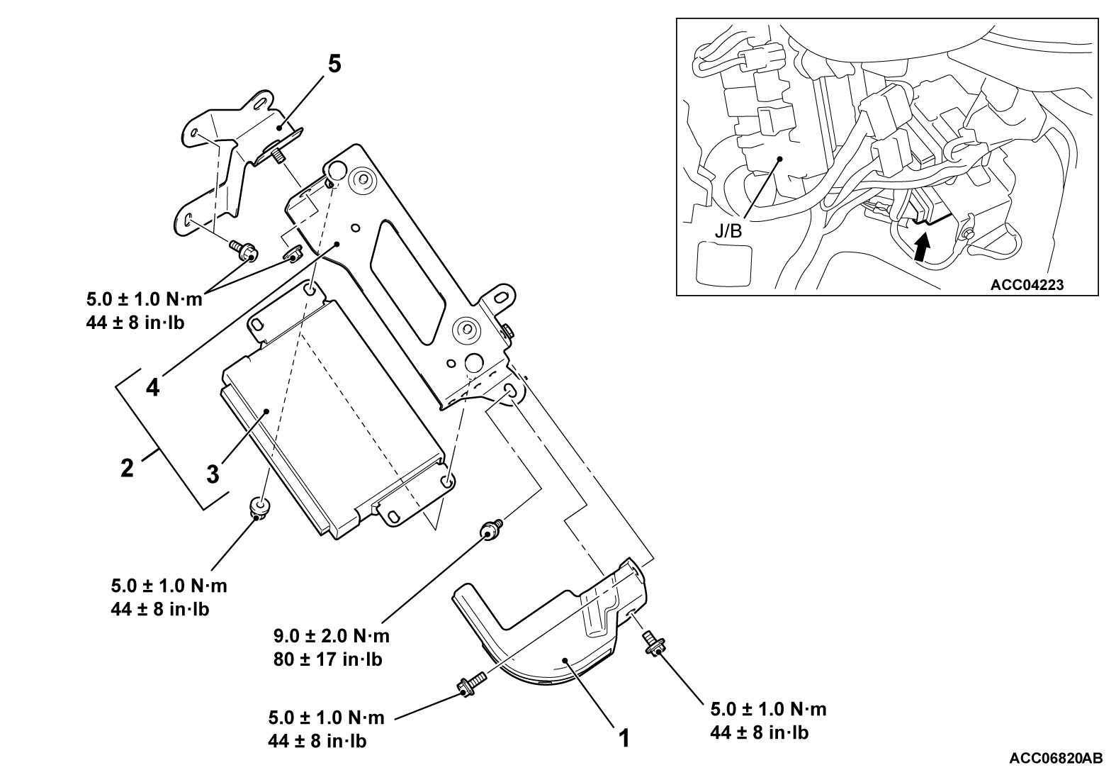
Removal steps
>>C<<Initialization operation.<only at installation>
1.Connector cover
>>A<<2.ECM and bracket assembly
3.ECM
TCM [Refer to GROUP 23A - Transaxle Control Module (TCM)]
4.ECM bracket
5.ECM bracket
<Vehicles for Canada>
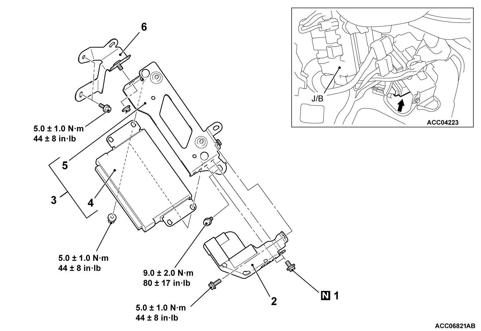
Removal steps
>>C<<Initialization operation (only at installation)
<<A>>>>B<<1.Break-off bolt
2.Connector cover
>>A<<3.ECM and bracket assembly
4.ECM
TCM [Refer to GROUP 23A - Transaxle Control Module (TCM)]
5.ECM bracket
6.ECM bracket
 
 
REMOVAL SERVICE POINT
 
 
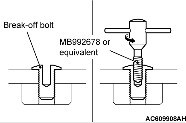
<<A>> BREAK-OFF BOLT REMOVAL
1. <When using recommended tool screw extractor set (MB992678) or equivalent>
(1) Drill in the break-off bolt a hole deep enough for the tap to stand.
(2) Use recommended tool screw extractor set (MB992678) or equivalent to remove the break-off bolt.

2. <When using the flat-tipped screwdriver>
(1) Apply force towards the direction to loose the bolt by a flat-tipped screwdriver.
(2) Remove the break-off bolt.


INSTALLATION SERVICE POINTS
 
 
>>A<< ECM AND BRACKET ASSEMBLY INSTALLATION
1. Tighten the ECM and bracket assembly mounting bolt temporarily.
2. Tighten the mounting nut to the specified torque.
Tightening torque: 5.0 ± 1.0 N·m (44 ± 8 in-lb)
3. Tighten the mounting bolt to the specified torque.
Tightening torque: 9.0 ± 2.0 N·m (80 ± 17 in-lb)


>>B<< BREAK-OFF BOLT INSTALLATION
Tighten until the head of break-off bolt is broken off.


>>C<< INITIALIZATION OPERATION
Turn the ignition switch to the "ON" position and then to "LOCK" (OFF) position and hold it for at least 10 seconds.