System Description
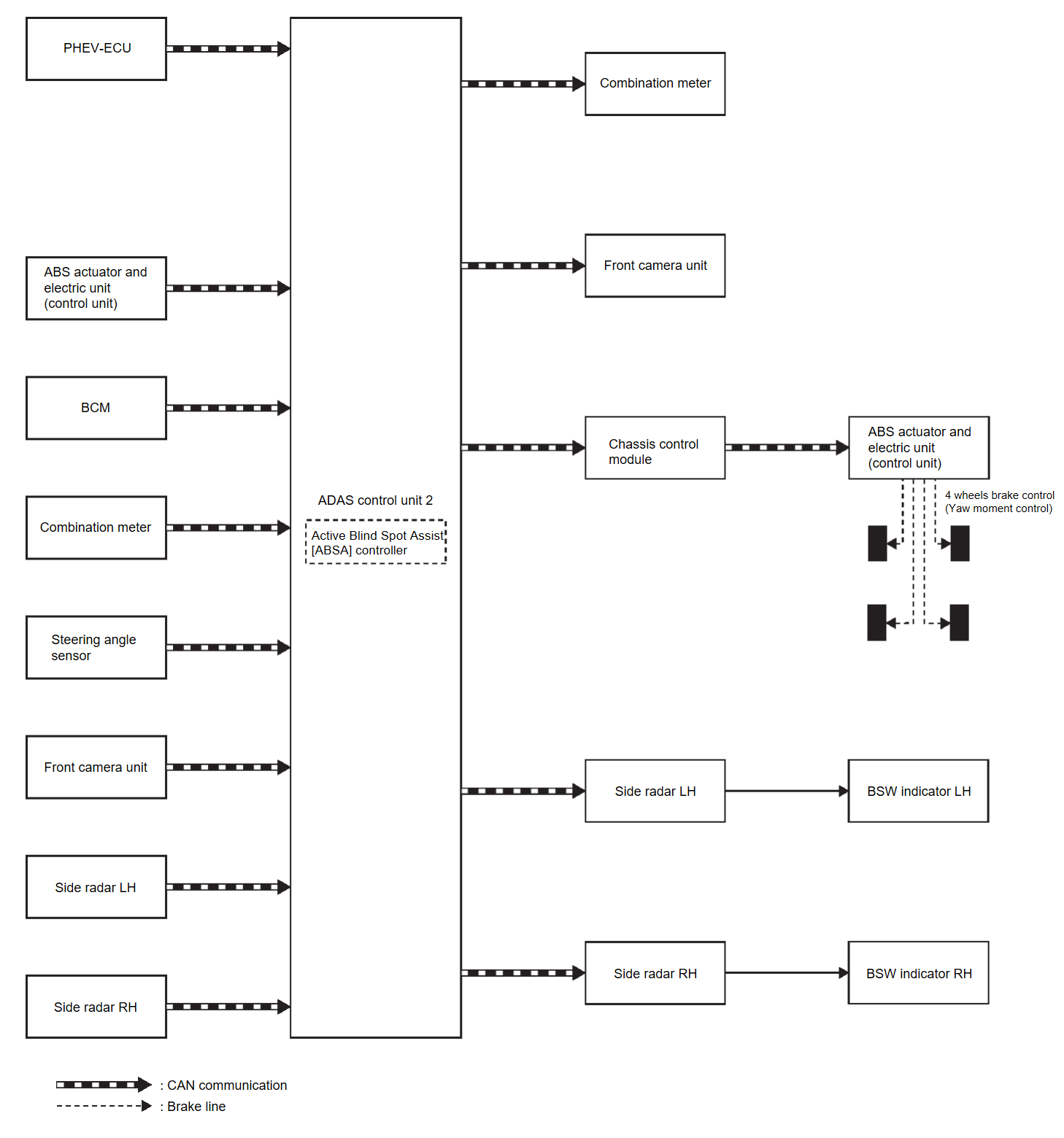
SYSTEM DIAGRAM
| Component | Description |
| PHEV-ECU | GENERAL INFORMATION |
| ABS actuator and electric unit (control unit) | ABS Actuator and Electric Unit (Control Unit) |
| BCM | System Description |
| Combination meter | Combination Meter |
| Steering angle sensor | Steering Angle Sensor |
| ADAS control unit 2 | ADAS Control Unit 2 |
| Side radar LH/RH | Side Radar LH/RH |
| Front camera unit | Front Camera Unit |
| BSW indicator LH, RH | BSW Indicator LH/RH |
| Chassis control module | Chassis Control Module |
ADAS CONTROL UNIT 2 INPUT/OUTPUT SIGNAL ITEM
Input Signal Item
| Transmit unit | Signal name | Description | |
| PHEV-ECU | CAN communication | Accelerator pedal position signal | Receives accelerator pedal position (angle) |
| Engine speed signal | Receives engine speed | ||
| Input speed signal | Receives the number of revolutions of input shaft | ||
| Current gear position signal | Receives a current gear position | ||
| Shift position signal | Receives a select lever position | ||
| Output shaft revolution signal | Receives the number of revolutions of output shaft | ||
| ABS actuator and electric unit (control unit) | CAN communication | ABS malfunction signal | Receives a malfunction state of ABS |
| ABS operation signal | Receives an operational state of ABS | ||
| TCS malfunction signal | Receives a malfunction state of TCS | ||
| TCS operation signal | Receives an operational state of TCS | ||
| ASC OFF signal | Receives an ON/OFF state of ESP | ||
| ASC malfunction signal | Receives a malfunction state of ESP | ||
| ASC operation signal | Receives an operational state of ESP | ||
| Vehicle speed signal (ABS) | Receives wheel speeds of four wheels | ||
| Yaw rate signal | Receives yaw rate acting on the vehicle | ||
| Side G sensor signal | Receives lateral G acting on the vehicle | ||
| BCM | CAN communication | Turn indicator signal | Receives an operational state of the turn signal light and the hazard light |
| Dimmer signal | Receives ON/OFF state of dimmer signal | ||
| Steering angle sensor | CAN communication | Steering angle sensor malfunction signal | Receives a malfunction state of steering angle sensor |
| Steering angle sensor signal | Receives the number of revolutions, turning direction of the steering wheel | ||
| Steering angle speed signal | Receives the turning angle speed of the steering wheel | ||
| Combination meter | CAN communication | System selection signal | Receives a selection state of each item selected with the information display |
| Front camera unit | CAN communication | Detected lane condition signal | Receives detection results of lane marker |
| Side radar LH, RH | CAN communication | Vehicle detection signal | Receives vehicle detection condition of detection zone |
Output Signal Item
| Reception unit | Signal name | Description | |
| ABS actuator and electric unit (via chassis control module) | CAN communication | Target yaw moment signal | Transmits a target yaw moment signal to generate yaw moment to the vehicle |
| Combination meter | CAN communication | Meter display signal | Transmits a signal to display a state of the system on the information display |
| Buzzer output signal | Transmits a signal to activate buzzer | ||
| Side radar LH, RH | CAN communication | Vehicle speed signal | Transmits a vehicle speed calculated by the ADAS control unit 2 |
| BSW indicator signal | Transmits a BSW indicator signal to turn ON the BSW indicator | ||
| BSW indicator dimmer signal | Transmits a BSW indicator dimmer signal to dimmer BSW indicator | ||
| Front camera unit | CAN communication | Vehicle speed signal | Transmits a vehicle speed calculated by ADAS control unit 2 |
| Turn indicator signal | Transmits a turn indicator signal received from BCM | ||
FUNCTION DESCRIPTION
- The Active Blind Spot Assist [ABSA] can help alert the driver of other vehicles in adjacent lanes when changing lanes. Active Blind Spot Assist [ABSA] always operates together with Blind Spot Warning.
- The Active Blind Spot Assist [ABSA] operates above approximately 60 km/h (37 MPH).
- The Active Blind Spot Assist [ABSA] uses side radar installed near the rear bumper to detect other vehicles beside vehicle in an adjacent lane.
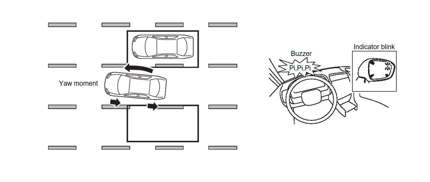
- The side radar can detect vehicles on either side of vehicle within the detection zone shown as illustrated.
- If the BSW indicator is illuminated while vehicle is approaching a lane marker, the BSW indicator blinks and an audible warning will sound three times. Then the system applies the brakes on one side of the vehicle for a short period of time to help return the vehicle back to the center of the lane.
- Active Blind Spot Assist [ABSA] operates regardless of turn signal usage.
- The brightness of BSW indicator lights is adjusted automatically depending on the brightness of the ambient light.
| note |
|
OPERATION DESCRIPTION
- ADAS control unit 2 enables Active Blind Spot Assist [ABSA].
- Turn ON the dynamic driver assistance switch, and Active Blind Spot Assist [ABSA] setting on the information display.
- Combination meter turns Active Blind Spot Assist [ABSA] display ON/OFF according to the signals from ADAS control unit 2 via CAN communication.
- Side radar detects a vehicle in the adjacent lane, and transmits the vehicle detection signal to ADAS control unit 2 via CAN communication.
- Side radar receives vehicle speed signal from ADAS control unit 2 and changes its detecting function.
- Front camera unit monitors lane markers of the traveling lane and transmits the detected lane condition signal to ADAS control unit 2 via CAN communication.
- ADAS control unit 2 starts the control as follows, based on a vehicle detection signal, lane condition signal, turn signal and position light request signal transmitted from BCM via CAN communication:
- BSW indicator signal and BSW indicator dimmer signal transmission to side radar.
- Calculation of necessary yaw moment and transmission of the target yaw moment signal to ABS actuator and electric unit (control unit).
- Side radar transmits an indicator operation signal to the BSW indicator according to BSW indicator operation signal and BSW indicator dimmer signal.
- ABS actuator and electric unit (control unit) controls brake pressure of four wheels respectively according to the target yaw moment signal.
OPERATION CONDITION
- Active Blind Spot Assist [ABSA]: ON
- Vehicle speed: Approximately 60 km/h (37 MPH) or more
| note |
|
CANCEL CONDITION
The ADAS control unit 2 cancels the operation when the system is under any conditions of the operation cancellation condition.
- When the system malfunction occurs.
- When the front camera unit becomes high temperature [over approximately 40 °C (104 °F)].
- When the area around the side radar is dirty.
- When the ASC or ABS (Including the TCS) operates.
- When the ASC is turned OFF
- When the SNOW mode, GRAVEL mode or MUD mode is selected (AWD models).
![[Previous]](../../../buttons/fprev.png)
![[Next]](../../../buttons/fnext.png)

