Diagnosis Procedure
1.CHECK CAMERA IMAGE SIGNAL CIRCUIT
- Turn electric motor switch OFF.
- Disconnect AV control unit harness connector and rear view camera harness connector.
- Check continuity between AV control unit harness connector and rear view camera harness connector.
AV control unit Rear view camera Continuity Connector Terminal Connector Terminal M102 49 D504 3 Existed - Check continuity between AV control unit harness connector and ground.
AV control unit Ground Continuity Connector Terminal M102 49 Not existed
Is the inspection result normal?
 Repair or replace harness or connectors.
2.CHECK CAMERA IMAGE SIGNAL
- Connect AV control unit harness connector and rear view camera harness connector.
- Turn electric motor switch ON.
- Shift the selector lever to “R” position.
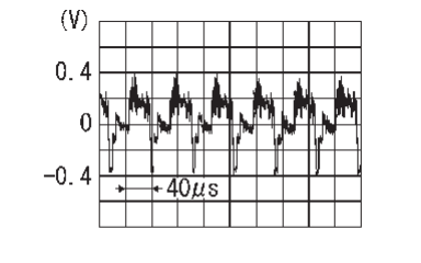
- Check signal between AV control unit harness connector and ground.
Is the inspection result normal?
 Replace AV control unit. Refer to Removal and Installation
 .
. Replace rear view camera. Refer to Removal and Installation
 .
.![[Previous]](../../../buttons/fprev.png)
![[Next]](../../../buttons/fnext.png)
