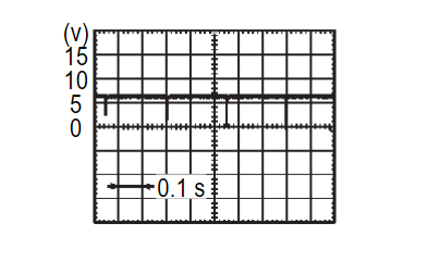
Diagnosis Procedure
1.CHECK FRONT SONAR SENSOR SIGNAL RH INNER CIRCUIT (OPEN)
- Turn electric motor switch OFF.
- Disconnect sonar control unit connector and front sonar sensor RH inner connector.
- Check continuity between sonar control unit harness connector and front sonar sensor RH inner connector
Sonar control unit Front sonar sensor RH inner Continuity Connector Terminal Connector Terminal B20 1 E306 2 Existed
Is the inspection result normal?
 Repair the harness or connector.
2.CHECK FRONT SONAR SENSOR RH INNER GROUND CIRCUIT
Check continuity between sonar control unit harness connector and front sonar sensor RH inner harness connector.
 Repair the harness or connector.
| Sonar control unit | front sonar sensor RH inner | Continuity | ||
| Connector | Terminal | Connector | Terminal | |
| B20 | 13 | E306 | 3 | Existed |
Is the inspection result normal?
 Repair the harness or connector.
3.CHECK FRONT SONAR SENSOR SIGNAL RH INNER
- Connect sonar control unit connector and front sonar sensor RH inner connector.
- Turn electric motor switch ON.
- Check the signal between sonar control unit terminals as per the following condition.
Is the inspection result normal?
 Replace the sonar control unit. Refer to Removal and Installation
 .
. Replace the front sonar sensor RH inner. Refer to Description
 .
.![[Previous]](../../../buttons/fprev.png)
![[Next]](../../../buttons/fnext.png)
