FRONT FOG LIGHT AIMING
PRE-AIMING INSTRUCTIONS
1. Inspect for rusted or faulty front fog light assemblies.
2. These conditions must be corrected before a satisfactory adjustment can be made.
3. Inspect tire inflation, and adjust if necessary.
4. If the fuel tank is not full, place a weight in the trunk of the vehicle to simulate weight of a full tank [3 kg (6.6 lb) per gallon].
5. There should be no other load in the vehicle other than driver or substituted weight of approximately 68 kg (150 lb) placed in driver's position.
6. Thoroughly clean the front fog light lenses.
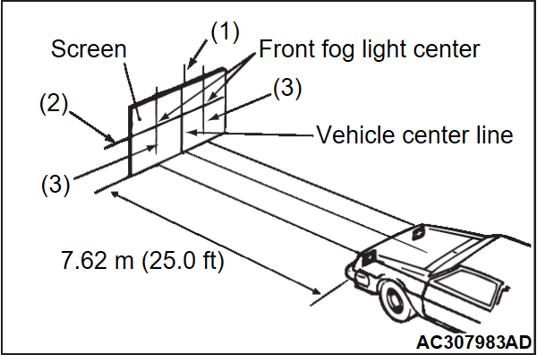
7. Place the vehicle on a level floor, perpendicular to a flat screen 7.62 m (25.0 ft) away from the bulb center-marks on the fog light lens.
8. Rock the vehicle sideways to allow the vehicle to assume its normal position.
9. Bounce the front suspension through three (3) oscillations by applying the body weight to the hood or bumper.
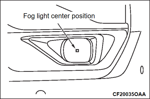
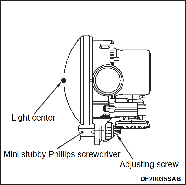
10. Measure the center of the front fog lights as shown in the illustration.
11. Four lines of adhesive tape (or equivalent markings) are required on screen or wall:
(1) Position a vertical tape or mark so that it is aligned with the vehicle center line.
(2) Measure the distance from the center of the front fog light lens to the floor. Transfer the measurement to the screen. Horizontal tape or mark on the screen is for reference of vertical adjustment.
(3) Measure the distance from the center line of the vehicle to the center of each front fog light. Transfer the measurement to the screen. Vertical tape or mark on the screen is for reference to the center line of each front fog light.
FOG LIGHT ADJUSTMENT
1. Turn the steering wheel all the way to the opposite side of the light being adjusted.
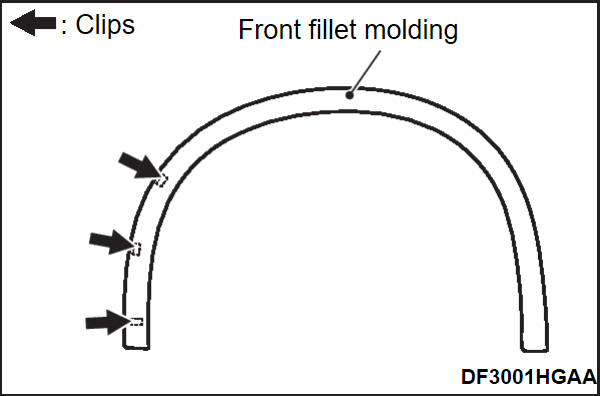
2. Partially remove the front fillet molding by remove the clips shown in the figure.
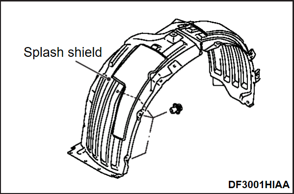
3. Remove the 3 clips of the front splash shield shown in the figure, and turn up the front splash shield.
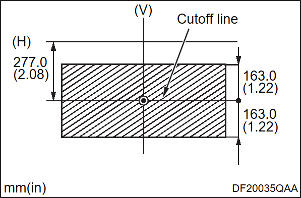
4. Adjust the cut off line (boundary between light and dark) position to the standard value with the adjusting screw.
5. Check if the beam shining onto the screen is at the standard value.
Standard value:
- (Cutoff line direction): The horizontal line 277.0 mm (10.91 in) (2.08 degrees angle) below the horizontal line (H)
Limit:
- (Vertical direction): Area from 163.0 mm (6.42 in) (1.22 degrees angle) above the cutoff line to 163.0 mm (6.42 in) (1.22 degrees angle) below the cutoff line
![[Previous]](../../../buttons/fprev.png)
![[Next]](../../../buttons/fnext.png)
