Diagnosis Procedure
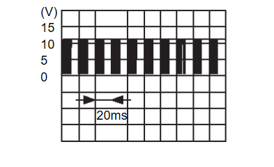
1.CHECK LIN COMMUNICATION SIGNAL
- Electric motor switch ON.
- Check signal between passenger door mirror control module harness connector and ground using an oscilloscope.
Is the inspection result normal?
2.CHECK PASSENGER DOOR MIRROR CONTROL MODULE CIRCUIT
- Electric motor switch OFF.
- Disconnect passenger door mirror control module connector and BCM connector.
- Check continuity between passenger door mirror control module harness connector and BCM harness connector.
Passenger door mirror control module BCM Continuity Connector Terminal Connector Terminal D108 7 M18 24 Existed - Check continuity between passenger door mirror control module harness connector and ground.
Passenger door mirror control module — Continuity Connector Terminal D108 7 Ground Not existed
Is the inspection result normal?
 Repair or replace harness.
3.REPLACE PASSENGER DOOR MIRROR CONTROL MODULE
Replace passenger door mirror control module. Refer to Removal and Installation .
. INSPECTION END
 .
.Is the inspection result normal?
 INSPECTION END
![[Previous]](../../../buttons/fprev.png)
![[Next]](../../../buttons/fnext.png)
