Diagnosis Procedure
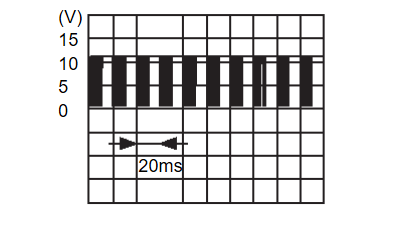
1.CHECK BCM OUTPUT SIGNAL
- Turn the power supply mode of the electric motor switch to ON.
- Check signal between BCM harness connector and ground using an oscilloscope.
Is the inspection result normal?
2.CHECK LIN COMMUNICATION CIRCUIT
- Electric motor switch OFF, and then wait for 3 minutes with driver door open.
note - Even after electric motor switch OFF, power is supplied to accessories for a certain amount of time by the AUTO ACC function.
- When vehicle is operated while on standby, power may be supplied to accessories.
- Disconnect following connectors.
- BCM
- Power window main switch
- Front power window motor (driver side)
- Passenger door mirror control module
- Sunroof motor assembly
- Sunshade motor assembly
Connecting parts other than power window. - Check continuity between BCM harness connector and ground.
BCM — Continuity Connector Terminal M18 24 Ground Not existed
Is the inspection result normal?
 Replace BCM. Refer to Removal and Installation
 .
. Repair or replace harness.
3.CHECK LIN COMMUNICATION SIGNAL
- Electric motor switch OFF, and then wait for 3 minutes with driver door open.
note - Even after electric motor switch OFF, power is supplied to accessories for a certain amount of time by the AUTO ACC function.
- When vehicle is operated while on standby, power may be supplied to accessories.
- Disconnect following connectors.
- Power window main switch
- Front power window motor (driver side)
- Turn the power supply mode of the electric motor switch to ON.
- Check signal between power window main switch harness connector, front power window motor (driver side) harness connector and ground using an oscilloscope.
Is the inspection result normal?
 INSPECTION END
 -1Power window main switch:
  .
. -2Front power window motor (driver side):
  .
.4.CHECK LIN COMMUNICATION CIRCUIT (POWER WINDOW MAIN SWITCH)
- Turn the power supply mode of the electric motor switch to OFF.
- Disconnect BCM connector.
- Check continuity between BCM harness connector and power window main switch harness connector.
BCM Power window main switch Continuity Connector Terminal Connector Terminal M18 24 D6 4 Existed
Is the inspection result normal?
 INSPECTION END
 Repair or replace harness.
5.CHECK LIN COMMUNICATION CIRCUIT [FRONT POWER WINDOW MOTOR (DRIVER SIDE)]
- Turn the power supply mode of the electric motor switch to OFF.
- Disconnect BCM connector.
- Check continuity between BCM harness connector and front power window motor (driver side) harness connector.
BCM Front power window motor (driver side) Continuity Connector Terminal Connector Terminal M18 24 D10 6 Existed
Is the inspection result normal?
 INSPECTION END
 Repair or replace harness.
![[Previous]](../../../buttons/fprev.png)
![[Next]](../../../buttons/fnext.png)
