Diagnosis Procedure
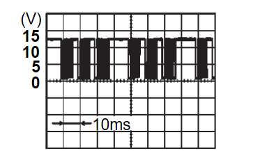
1.CHECK BACK DOOR SERIAL COMMUNICATION SIGNAL
- Turn the power supply mode of the electric motor switch to ON.
- Check signal between BCM harness connector and ground using oscilloscope.
Is the inspection result normal?
 INSPECTION END
2.CHECK BACK DOOR SERIAL COMMUNICATION CIRCUIT
- Turn the power supply mode of the electric motor switch to OFF.
- Disconnect hands free sensor control unit connector and BCM connector.
- Check continuity between hands free sensor control unit harness connector and BCM harness connector.
Hands free sensor control unit BCM Continuity Connector Terminal Connector Terminal B452 1 B26 83 Existed - Check continuity between hands free sensor control unit harness connector and ground.
Hands free sensor control unit — Continuity Connector Terminal B452 1 Ground Not existed
Is the inspection result normal?
 Replace BCM. Refer to Removal and Installation
 .
. Repair or replace harness.
![[Previous]](../../../buttons/fprev.png)
![[Next]](../../../buttons/fnext.png)
