[Previous][Next]
Disassembly and Assembly
warningBefore disassembly and assembly the front seat assembly, refer to "BODY INTERIOR - SEAT - PRECAUTION - PRECAUTIONS".
  • To prevent accidental explosion, always place the front side air bag module with deploying direction facing upward and never insert any foreign objects (screwdriver, etc.) into the front side air bag module.
noteWhen the front seatback frame or front seat cushion frame with memory function is replaced, it is necessary to reset the seat position.
 
 
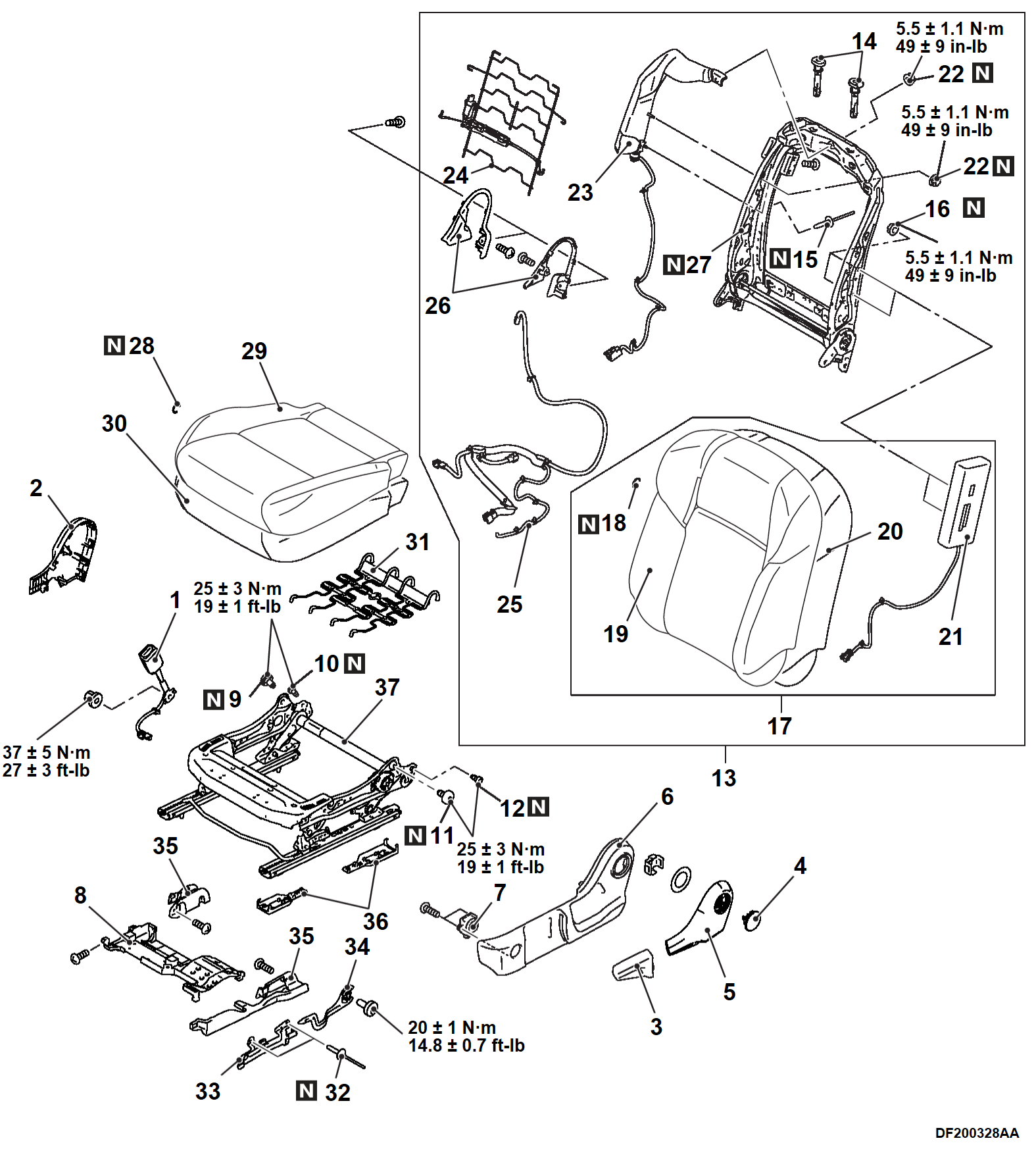
<DRIVER'S SEAT (MANUAL SEAT)>
Disassembly steps
1.Seat belt buckle
2.Inside seat cushion finisher outer
3.Lifter knob
4.Reclining knob cap
5.Reclining knob
6.Outside seat cushion finisher outer
7.Lumbar support switch
8.Bracket
9.Bolt A
10.Bolt B
11.Bolt C
12.Bolt D
13.Seatback assembly
14.Headrest holder
15.Rivet A
16.Nut A
17.Front side air bag module, seatback pad and trim
18.Cover ring A
19.Seatback trim
20.Seatback pad
21.Front side air bag module
22.Nut B
23.Front center air bag module
24.Front seat lumbar support assembly
25.Seat harness
26.Side seat cushion finisher inner
27.Seatback frame
28.Cover ring B
29.Seat cushion trim
30.Seat cushion pad
31.Seat cushion suspension
32.Rivet B
33.Outside seat cushion finisher bracket
34.Lifter lever
35.Side seat cushion finisher lower
36.Seat cushion lower end cap
37.Seat cushion frame
 
 
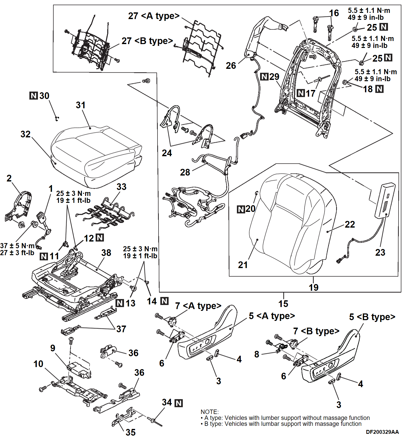
<DRIVER'S SEAT (POWER SEAT)>
Disassembly steps
1.Seat belt buckle
2.Inside seat cushion finisher outer
3.Slide knob
4.Reclining knob
5.Outside seat cushion finisher outer
6.Power seat switch
7.Lumbar support switch
8.Seatback massager power unit <B type>
9.Driver seat control unit <Vehicles with automatic drive positioner system>
10.Bracket
11.Bolt A
12.Bolt B
13.Bolt C
14.Bolt D
15.Seatback assembly
16.Headrest holder
17.Rivet A
18.Nut A
19.Front side air bag module, seatback pad and trim
20.Cover ring A
21.Seatback trim
22.Seatback pad
23.Front side air bag module
24.Side seat cushion finisher inner
25.Nut B
26.Front center air bag module
27.Front seat lumbar support assembly
28.Seat harness
29.Seatback frame
30.Cover ring B
31.Seat cushion trim
32.Seat cushion pad
33.Seat cushion suspension
34.Rivet B
35.Outside seat cushion finisher bracket
36.Side seat cushion finisher lower
37.Seat cushion lower end cap
38.Seat cushion frame
 
 
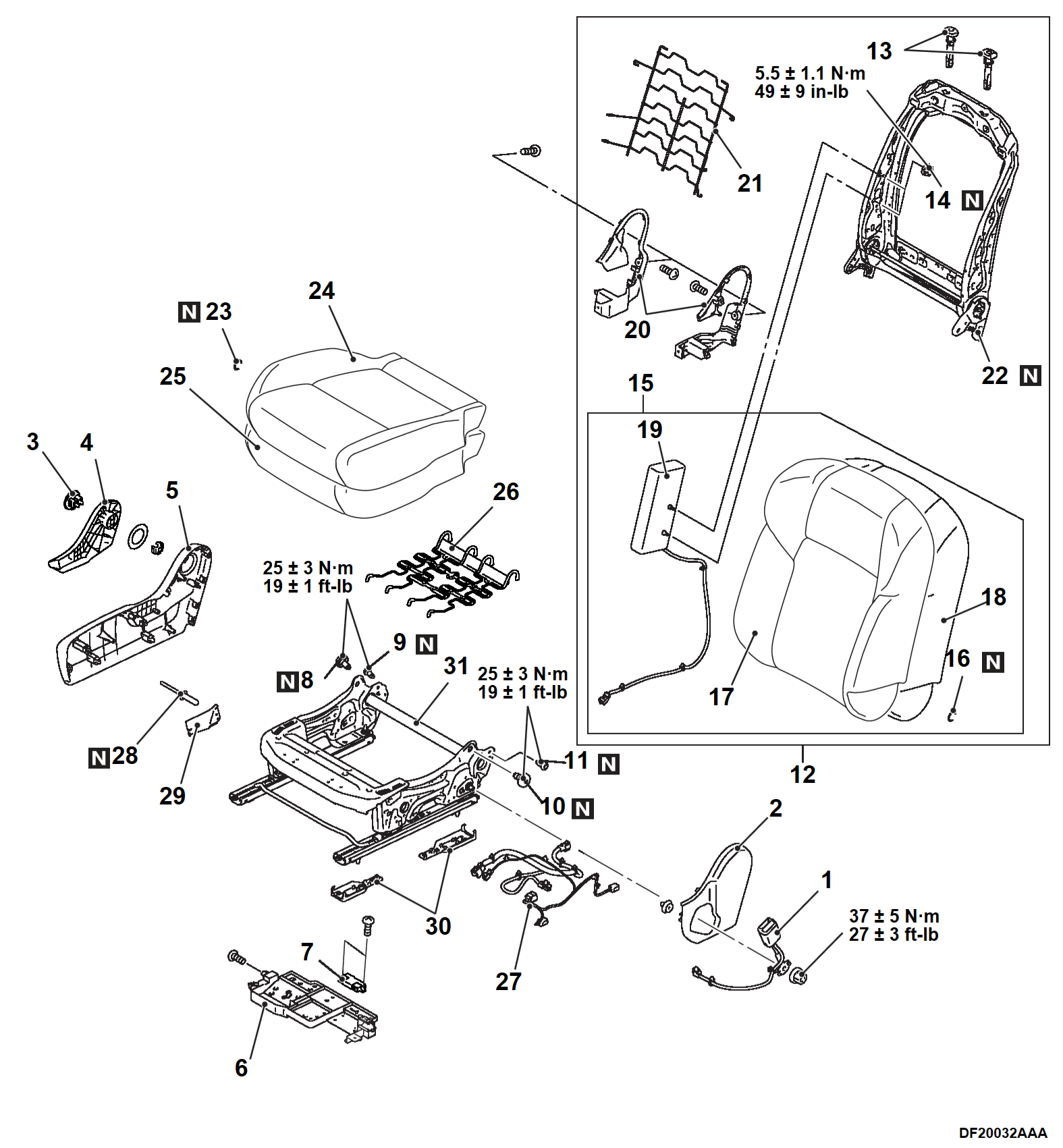
<PASSENGER'S SEAT (MANUAL SEAT)>
Disassembly steps
1.Seat belt buckle
2.Inside seat cushion finisher outer
3.Reclining knob cap
4.Reclining knob
5.Outside seat cushion finisher outer
6.Bracket A
7.Occupant detection system control unit
8.Bolt A
9.Bolt B
10.Bolt C
11.Bolt D
12.Seatback assembly
13.Headrest holder
14.Nut
15.Front side air bag module, seatback pad and trim
16.Cover ring A
17.Seatback trim
18.Seatback pad
19.Front side air bag module
20.Side seat cushion finisher inner
21.Seatback suspension
22.Seatback frame
23.Cover ring B
24.Seat cushion trim
25.Seat cushion pad
26.Seat cushion suspension
27.Seat harness
28.Rivet
29.Bracket B
30.Seat cushion lower end cap
31.Seat cushion frame
 
 
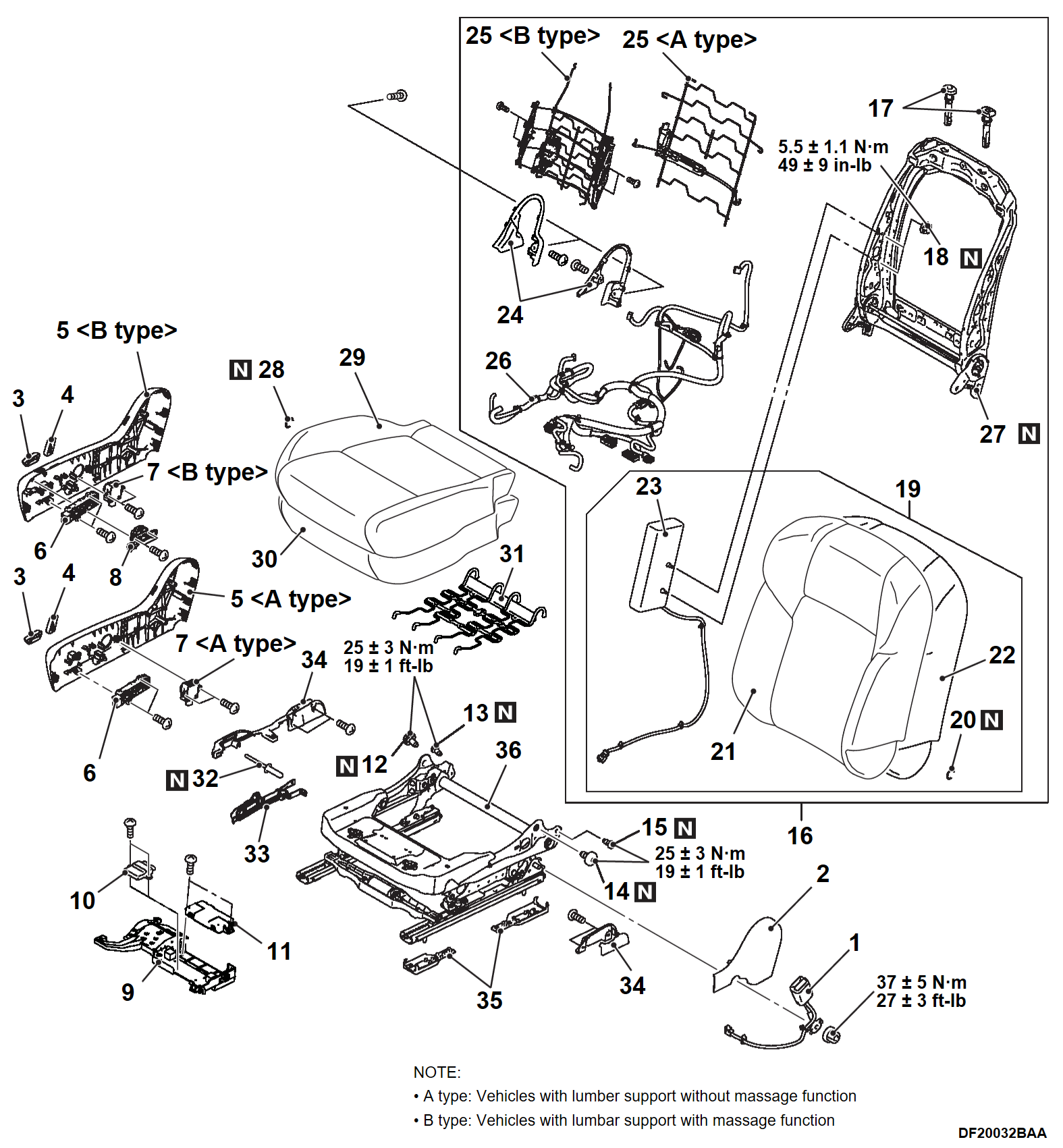
<PASSENGER'S SEAT (POWER SEAT)>
Disassembly steps
1.Seat belt buckle
2.Inside seat cushion finisher outer
3.Slide knob
4.Reclining knob
5.Outside seat cushion finisher outer
6.Power seat switch
7.Lumber support switch
8.Seatback massager power unit <B type>
9.Bracket
10.Occupant detection system control unit
11.Passenger seat control unit
12.Bolt A
13.Bolt B
14.Bolt C
15.Bolt D
16.Seatback assembly
17.Headrest holder
18.Nut
19.Front side air bag module, seatback pad and trim
20.Cover ring A
21.Seatback trim
22.Seatback pad
23.Front side air bag module
24.Side seat cushion finisher inner
25.Front seat lumbar support assembly
26.Seat harness
27.Seatback frame
28.Cover ring B
29.Seat cushion trim
30.Seat cushion pad
31.Seat cushion suspension
32.Rivet
33.Outside seat cushion finisher bracket
34.Side seat cushion finisher lower
35.Seat cushion lower end cap
36.Seat cushion frame
 
 
DISASSEMBLY SERVICE POINTS
 
 
<<A>> HEADREST HOLDER REMOVAL
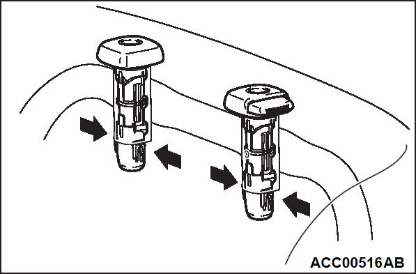
Remove the headrest holder while pushing the on both sides inward.


<<B>> RIVETS REMOVAL
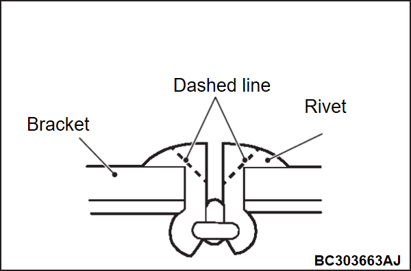
Using a drill, grind the rivet to the dotted line and break it.


ASSEMBLY SERVICE POINTS
 
 
>>A<< RIVETS INSTALLATION
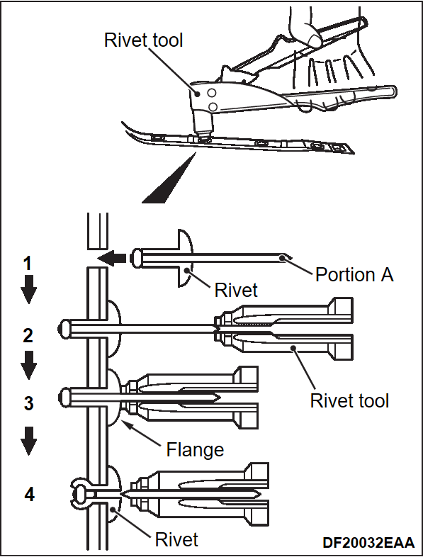
Use a rivet tool shown as in the illustration to connect the parts with rivets by the following procedures:
1. Insert the rivet into a corresponding location.
2. Set the rivet tool at a portion A of rivet.
3. While pushing the flange surface of the rivet onto parts to be fixed with the rivet tool, press the handle of the tool.
4. Thin part of portion A of the rivet will be cut off and the part is fixed in position.


>>B<< FRONT SEAT NUT / FRONT SEATBACK FRAME INSTALLATION
Replace the front seat nut and the front seatback frame with new ones.
cautionDo not reuse the front seatback frame and the front seat nut because the fastening force may be reduced.
1. Temporarily tighten front seat nuts.
2. First tighten the lower front seat nut to the specified torque, and then tighten the upper front seat nut to the specified torque.
Tightening torque: 5.5 ± 1.1 N·m


>>C<< FRONT SEAT LUMBAR SUPPORT ASSEMBLY INSTALLATION <VEHICLES WITH MASSAGE FUNCTION>
cautionWhen the lumbar unit on the front seat with massage function is replaced, be sure to relearn the driver seat control unit or passenger seat control unit.