Diagnosis Procedure
| note | If all of door motor DTCs are detected, check this circuit. |
1.CHECK DOOR MOTOR POWER SUPPLY
- Change the power supply mode of the electric motor switch to ON (READY indicator: ON).
- Check voltage between intake door motor harness connector and A/C amp. harness connector.
| + | − | Voltage | ||
| Intake door motor | A/C amp. | |||
| Connector | Terminal | Connector | Terminal | |
| M147 | 1 | M54 | 1 | 10.5 – 16 V |
Is the inspection result normal?
2.CHECK DOOR MOTOR GROUND CIRCUIT FOR OPEN
- Turn the electric motor switch OFF.
- Disconnect intake door motor connector and A/C amp. connector.
- Check continuity between intake door motor harness connector and A/C amp. harness connector.
Intake door motor A/C amp. Continuity Connector Terminal Connector Terminal M147 2 M54 27 Existed
Is the inspection result normal?
 Repair harness or connector.
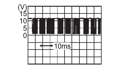
3.CHECK DOOR MOTOR LIN SIGNAL
- Connect intake door motor connector and A/C amp. connector.
- Change the power supply mode of the electric motor switch to ON (READY indicator: ON).
- Confirm output waveform between intake door motor harness connector and A/C amp. harness connector with oscilloscope.
Is the inspection result normal?
 INSPECTION END
4.CHECK DOOR MOTOR LIN SIGNAL CIRCUIT FOR OPEN
- Turn the electric motor switch OFF.
- Disconnect A/C amp. and intake door motor connector.
- Check continuity between intake door motor harness connector and A/C amp. harness connector.
Intake door motor A/C amp. Continuity Connector Terminal Connector Terminal M147 1 M54 1 Existed
Is the inspection result normal?
 Repair harness or connector.
5.CHECK DOOR MOTOR LIN SIGNAL CIRCUIT FOR SHORT
- Turn the electric motor switch OFF.
- Disconnect following connectors.
- Air mix door motor (passenger side)
- Air mix door motor (driver side)
- Air mix door motor (rear)
- Mode door motor
- Check continuity between A/C amp. harness connector and ground.
A/C amp. — Continuity Connector Terminal M54 2 Ground Not existed
Is the inspection result normal?
 Replace A/C amp. Refer to Removal and Installation
 .
. Repair harness or connector.
6.CHECK DOOR MOTOR POWER SUPPLY CIRCUIT FOR OPEN
- Turn the electric motor switch OFF.
- Disconnect intake door motor and A/C amp. connector.
- Check continuity between intake door motor harness connector and A/C amp. harness connector.
Intake door motor A/C amp. Continuity Connector Terminal Connector Terminal M147 1 M54 1 Existed
Is the inspection result normal?
 Repair harness or connector.
7.CHECK DOOR MOTOR POWER SUPPLY CIRCUIT FOR SHORT
- Disconnect following connectors.
- Air mix door motor (passenger side)
- Air mix door motor (driver side)
- Air mix door motor (rear)
- Mode door motor
- Check continuity between A/C amp. harness connector and ground.
A/C amp. — Continuity Connector Terminal M54 1 Ground Not existed
Is the inspection result normal?
 Replace A/C amp. Refer to Removal and Installation
 .
. Repair harness or connector.
![[Previous]](../../../buttons/fprev.png)
![[Next]](../../../buttons/fnext.png)
