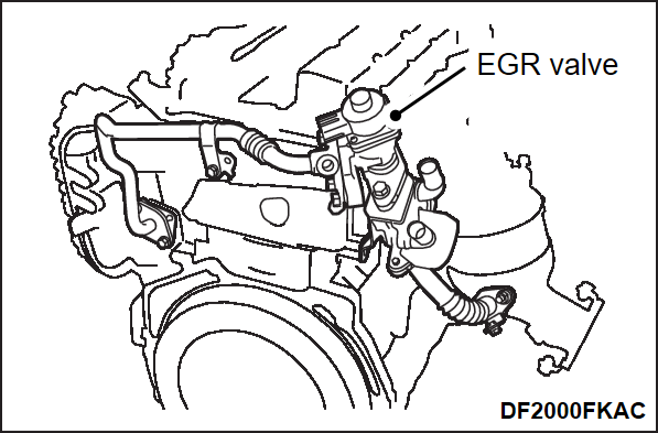
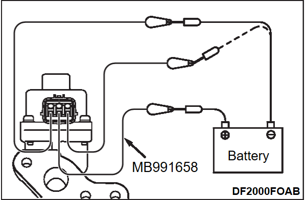
EGR VALVE (STEPPER MOTOR) CHECK
Required Special Tool:
- MB991658: Test Harness Set
CHECKING THE OPERATION SOUND
1. Check that the operation sound of the stepper motor can be heard from the EGR valve when the power supply mode of the electric motor switch is ON.
CHECKING THE COIL RESISTANCE
1. Disconnect the EGR valve connector.
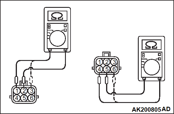
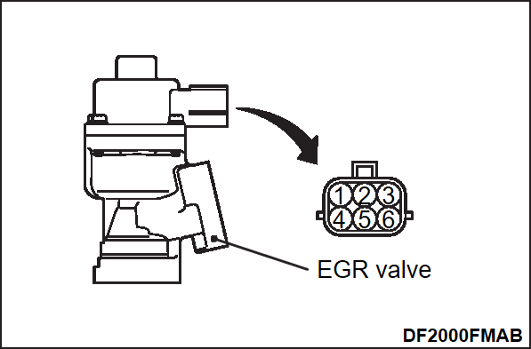
2. Measure the resistance between terminal No. 2 and either terminal No. 1 or terminal No. 3 of the connector at the EGR valve.
Standard value: 20 – 24 Ω [at 20°C (68°F)]
3. Measure the resistance between terminal No. 5 and either terminal No. 4 or terminal No. 6 of the connector at the EGR valve.
Standard value: 20 – 24 Ω [at 20°C (68°F)]
4. If the value deviates from the standard value, replace the EGR valve.
OPERATION CHECK
1. Remove the EGR valve.
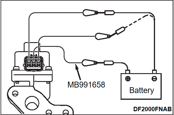
2. Attach a special tool test harness (MB991658) to the connector at the EGR valve.
| caution | Connecting battery voltage to the EGR valve for a long term could damage the coil. |
3. Connect the positive (+) terminal of the battery to terminal No. 2.
4. Connect terminals No. 1 and No. 3 to the negative (-) terminal of the battery, in order to test whether the stepper motor vibrates (with a slight shudder), indicating that the stepper motor is operating.
| caution | Connecting battery voltage to the EGR valve for a long term could damage the coil. |
5. Connect the positive (+) terminal of the battery to terminal No. 5.
6. Connect terminals No. 4 and No. 6 to the negative (-) terminal of the battery, in order to test whether the stepper motor vibrates (with a slight shudder), indicating that the stepper motor is operating.
7. If a vibration can be felt during the test, the stepper motor is normal.
8. Using a new gasket, install the EGR valve by tightening its mounting bolts to the specified torque.
Tightening Torque: 21 ± 3 N·m (16 ± 1 ft-lb)
![[Previous]](../../../buttons/fprev.png)
![[Next]](../../../buttons/fnext.png)
