REMOVAL AND INSTALLATION
| caution |
|
REMOVAL SERVICE POINT
INSTALLATION SERVICE POINTS
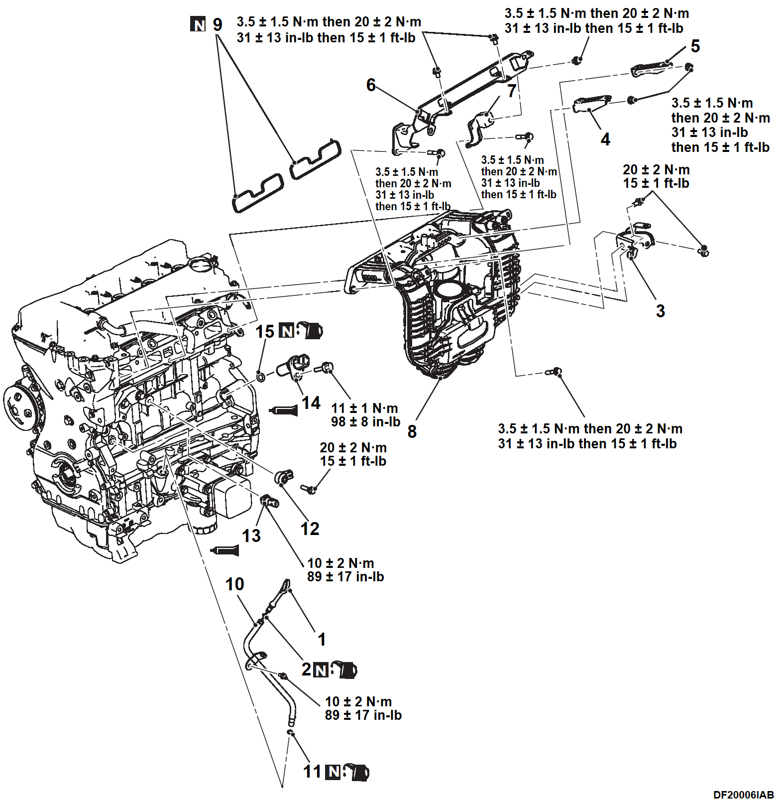
>>A<< CRANKSHAFT POSITION SENSOR INSTALLATION
| caution | Never apply force of twisting, torsion, etc. to the O-ring when mounting the sensor. |
>>B<< ENGINE OIL PRESSURE SWITCH INSTALLATION
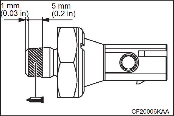
| caution | Make sure that the sealant does not stick out to the screw tip. |
1. Apply sealant to the engine oil pressure switch thread.
Specified sealant: ThreeBond 1215 or equivalent
| note | Install the engine oil pressure switch immediately after applying sealant. |
| caution | After the installation, until a sufficient period of time (one hour or more) elapses, do not apply the engine oil or water to the sealant application area or start the engine. |
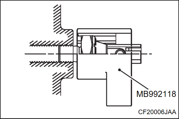
2. In the same manner as removal, use special tool oil pressure switch wrench (MB992118) to tighten the engine oil pressure switch to the specified torque.
Tightening torque: 10 ± 2 N·m (89 ± 17 in-lb)
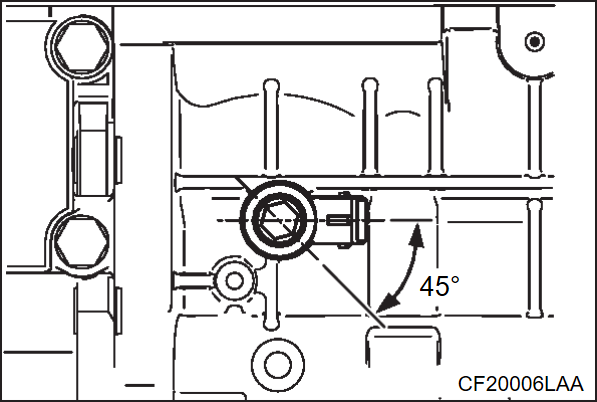
>>C<< KNOCK SENSOR INSTALLATION
Set the connector of the knock sensor to the area shown in the figure, and tighten the knock sensor to the specified torque.
Tightening torque: 20 ± 2 N·m (15 ± 1 ft-lb)
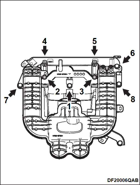
>>D<< INLET MANIFOLD/FUEL TUBE PROTECTOR STAY/FUEL TUBE PROTECTOR/INLET MANIFOLD STAY INSTALLATION
1. Temporarily tighten the mounting bolts and nuts for the inlet manifold, fuel tube protector stay and fuel tube protector in the numerical order as shown in the figure.
Tightening torque: 3.5 ± 1.5 N·m (31 ± 13 in-lb)
2. Tighten again the mounting bolts and nuts to the specified torque in the order shown in the illustration.
Tightening torque: 20 ± 2 N·m (15 ± 1 ft-lb)
3. Temporarily tighten the inlet manifold stay and make sure the mounting surface of the inlet manifold stay is in close contact and tighten the mounting bolts to the specified torque.
Tightening torque: 20 ± 2 N·m (15 ± 1 ft-lb)
![[Previous]](../../../buttons/fprev.png)
![[Next]](../../../buttons/fnext.png)
