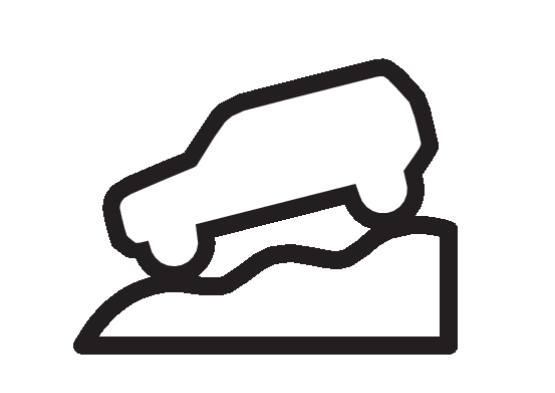
Hill Descent Control System Indicator Light
DESIGN/PURPOSE
- The hill descent control system indicator informs the driver that the hill descent control function is operating or ready to operate.
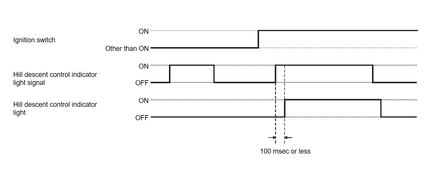
BULB CHECK
Approximately 1 second after the ignition switch is turned on.
SYNCHRONIZATION WITH MASTER WARNING LIGHT
Not applicable
OPERATION AT COMBINATION METER CAN COMMUNICATION CUT-OFF OR UNUSUAL SIGNAL
For actions on CAN communications blackout in the combination meter, refer to Fail-Safe .
.
 .
.SIGNAL PATH
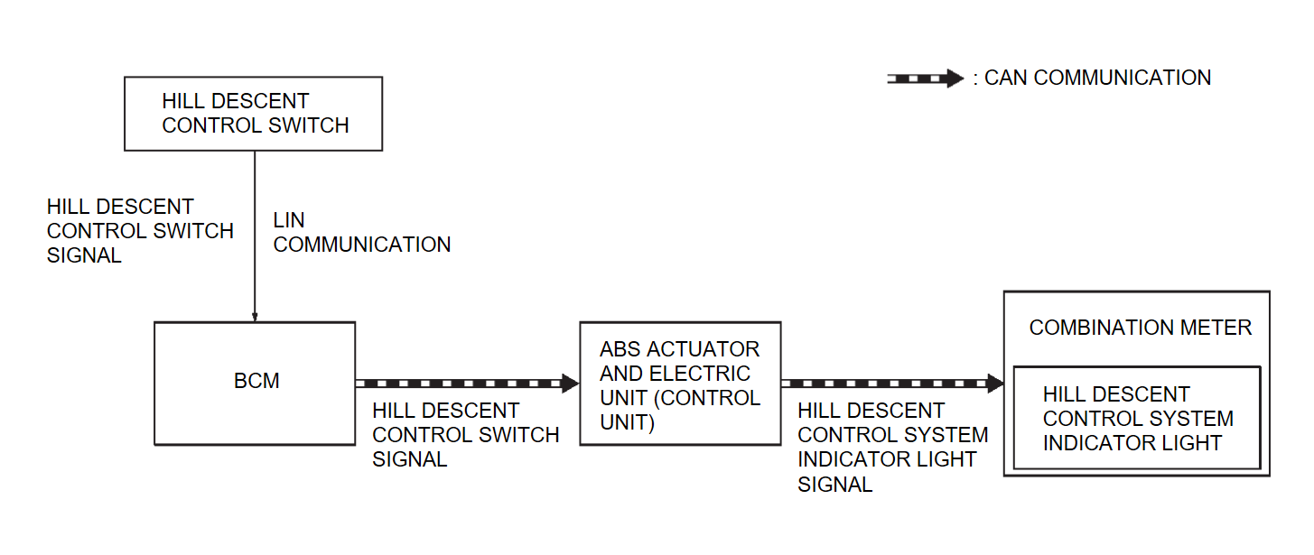
- The ABS actuator and electric unit (control unit) receives the hill descent control switch signal from the hill descent control switch via BCM.
- The ABS actuator and electric unit (control unit) sends the hill descent control system indicator light signal to the combination meter via CAN communication based on the hill descent control switch signal and the vehicle status.
- When the combination meter receives the hill descent control system indicator light signal, it turns on or blinks the hill descent control system indicator light.
LIGHTING CONDITION
When all of the following conditions are satisfied:
- Ignition switch ON
- When the hill descent control function is operating
- The hill descent control operable state (when the conditions are satisfied)
BLINKING CONDITION
The hill descent control operable state (when the conditions are not satisfied)
SHUTOFF CONDITION
- Hill descent control switch: OFF
- ASC warning light: ON
- Brake system: brake temperature high
- Ignition switch is OFF
![[Previous]](../../../buttons/fprev.png)
![[Next]](../../../buttons/fnext.png)


