SRS Air Bag Warning Light
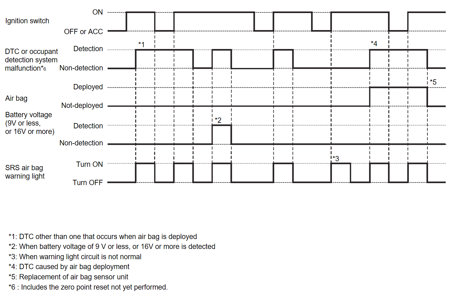
BULB CHECK
For 7 seconds after the ignition switch is turned ON.
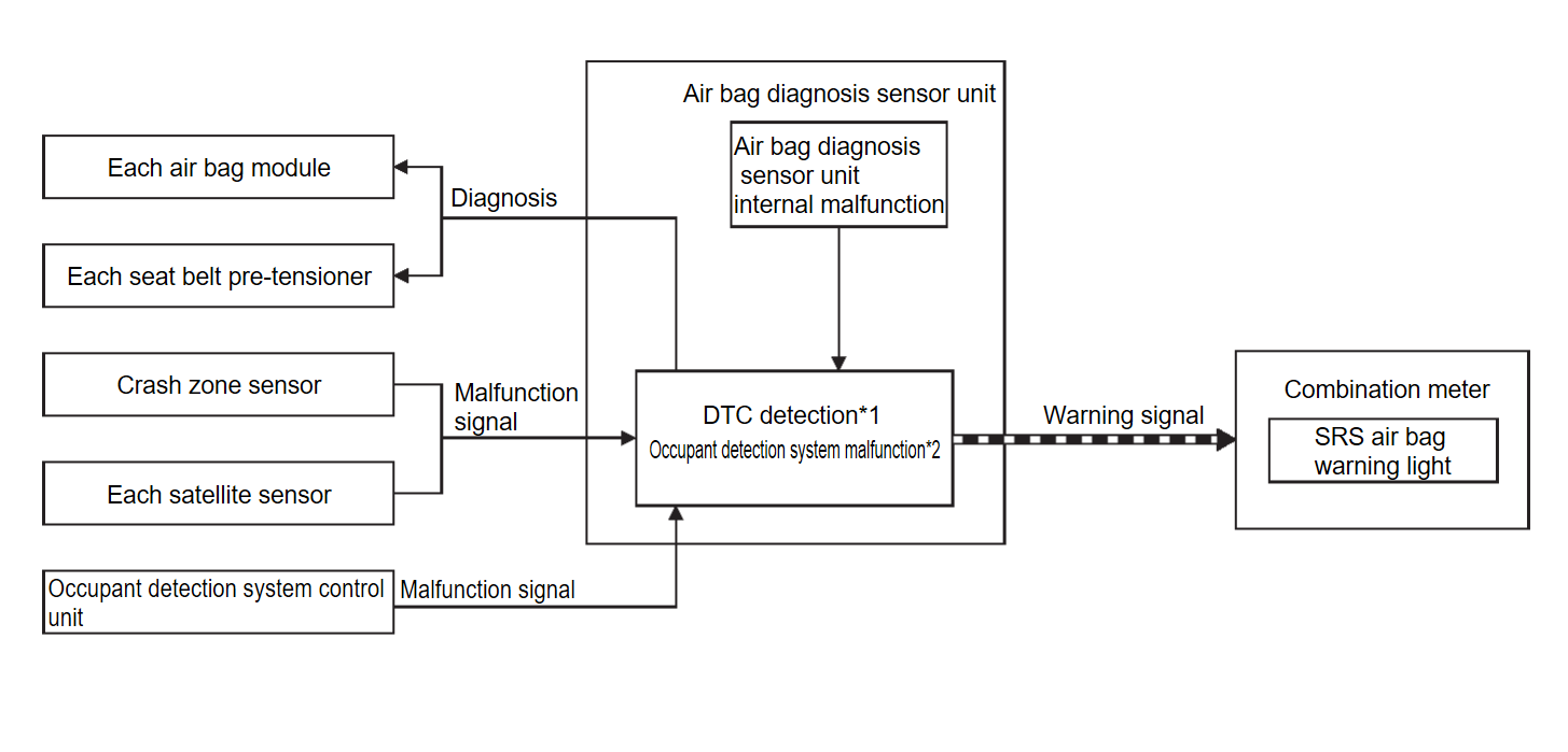
SYSTEM DIAGRAM
| note |
|
SIGNAL PATH
- When a malfunction is detected, air bag diagnosis sensor unit transmits the warning signal to combination meter.
- Combination meter turns SRS air bag warning light ON, according to the received signal.
LIGHTING CONDITION
When a malfunction of the following part or status is detected.
- Deployment of air bag
- Air bag diagnosis sensor unit
- Combination meter
- Circuit between air bag diagnosis sensor unit and combination meter
- Battery voltage not normal (approximately 9 V or less, or 16 V or more)
- Each air bag module main unit
- Each seat belt pre-tensioner main unit
- Crash zone sensor main unit
- Each satellite sensor
- Circuit between each air bag module and air bag diagnosis sensor unit
- Circuit between each seat belt pre-tensioner and air bag diagnosis sensor unit
- Circuit between crash zone sensor and air bag diagnosis sensor unit
- Circuit between each satellite sensor and air bag diagnosis sensor unit
- Occupant detection system control unit (Includes the zero point reset not yet performed.)
| note | For the relation between warning light and DTC, refer to DTC Index . . |
SHUTOFF CONDITION
When Being Turned ON Due to Deployment of Air Bag
Replace air bag diagnosis sensor unit.
When Turned ON Due to a Malfunction of SRS Air Bag Warning Light Circuit
Repair SRS air bag warning light circuit system.
When Turned ON Due to a Malfunction of Air Bag Module or Air Bag Module Circuit
Repair the malfunctioning part. Erase self-diagnosis result memory.
When Turned ON Due to a Malfunction of Occupant Detection System Control Unit
- Perform the zero point reset.
- Replace Occupant detection system control unit or the malfunction parts.
![[Previous]](../../../buttons/fprev.png)
![[Next]](../../../buttons/fnext.png)


