System Description
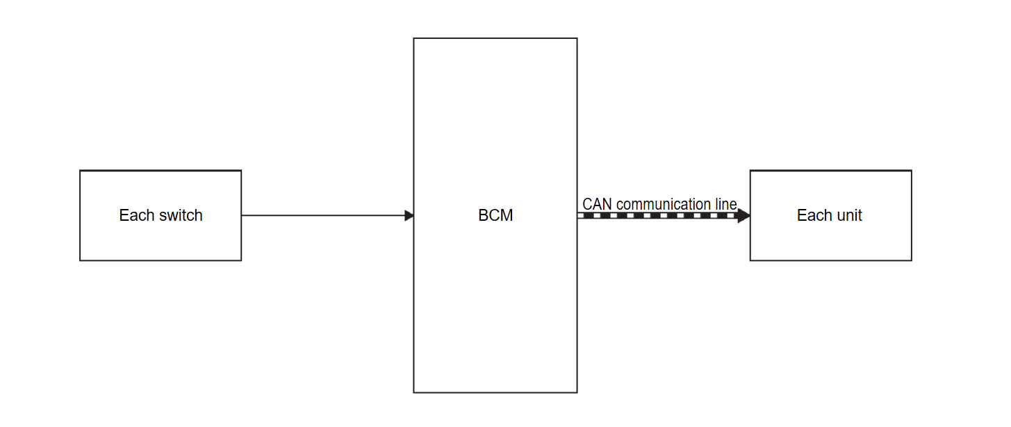
SYSTEM DIAGRAM
| Parts name | System description |
| Each switch (sensor) | Outputs the each signal to BCM. |
| BCM | BCM has the signal transmission function that outputs/transmits each input/received signal to each unit. |
| Each unit | Inputs the each signal from BCM. |
OUTLINE
BCM has the signal transmission function that transmits each input signal to each unit.
Signal transmission function list
| Signal name | Input | Output | Description |
| Door switch signal | Each door switch |
| Inputs the each door switch signal and transmits the door switch signal judged with BCM via CAN communication. |
| Drive mode switch signal | Drive mode switch | Chassis control module | Inputs the drive mode switch signal and transmits the drive mode switch signal judged with BCM via CAN communication. |
| Seat belt buckle switch (driver side) signal | Front seat belt buckle switch LH |
| Inputs the front seat belt buckle switch LH signal and transmits the seat belt buckle switch (driver side) signal judged with BCM via CAN communication. |
| Stop light switch signal | Stop light switch |
| Inputs the stop light switch signal and transmits stop light switch signal via CAN communication. |
| Brake pedal position switch signal | Stop light switch | ADAS control unit 2 | Inputs the stop light switch signal and transmits the brake pedal position switch signal judged with BCM via CAN communication. |
| Combination switch reading function | Combination switch |
| Inputs the combination switch reading function and transmits the each combination switch signal judged with BCM via CAN communication. |
![[Previous]](../../../buttons/fprev.png)
![[Next]](../../../buttons/fnext.png)
