Diagnosis Procedure
1.CHECK NATS ANTENNA AMP. COMMUNICATION SIGNAL
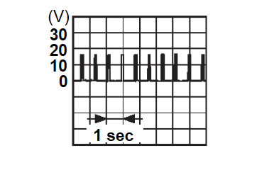
Check signal between push-button ignition switch harness connector and ground using an oscilloscope.
| (+) | (–) | Condition | Signal (Reference value) | ||
| Push-button ignition switch | |||||
| Connector | Terminal | ||||
| M17 | 2 | Ground | Keyless operation key battery is removed and brake pedal is depressed | When a registered Keyless operation key backside is contacted to push-button ignition switch | 0 V |
| Other than above | |||||
| 3 | When a registered Keyless operation key backside is contacted to push-button ignition switch | 0 V | |||
| Other than above | |||||
Is the inspection result normal?
2.CHECK NATS ANTENNA AMP. COMMUNICATION SIGNAL CIRCUIT
- Ignition switch OFF.
- Disconnect Keyless operation key unit connector and push-button ignition switch connector.
- Check continuity between push-button ignition switch harness connector and Keyless operation key unit harness connector.
Push-button ignition switch Keyless operation key unit Continuity Connector Terminal Connector Terminal M17 2 M184 19 Existed 3 20 - Check continuity between push-button ignition switch harness connector and ground.
Push-button ignition switch — Continuity Connector Terminal M17 2 Ground Not existed 3
Is the inspection result normal?
 Repair or replace harness.
3.REPLACE PUSH-BUTTON IGNITION SWITCH
Replace push-button ignition switch. Refer to Removal and Installation .
. INSPECTION END
 .
.Is the inspection result normal?
 INSPECTION END
4.REPLACE INTELLIGENT KEY UNIT
Replace Keyless operation key unit. Refer to Removal and Installation .
.
 .
. : INSPECTION END
![[Previous]](../../../buttons/fprev.png)
![[Next]](../../../buttons/fnext.png)
