Diagnosis Procedure
1.CHECK IN-VEHICLE SENSOR SIGNAL
- Ignition switch ON.
- Check voltage between A/C amp. harness connector.
Is the inspection result normal?
 Replace A/C amp. Refer to A/C AMP. REMOVAL AND INSTALLATION
 .
.2.CHECK IN-VEHICLE SENSOR POWER SUPPLY
- Ignition switch OFF.
- Disconnect in-vehicle sensor connector.
- Ignition switch ON.
- Check voltage between in-vehicle sensor harness connector and ground.
+ - Voltage (Approx.)In-vehicle sensor Connector Terminal M41 1 Ground 5 V
Is the inspection result normal?
3.CHECK IN-VEHICLE SENSOR GROUND CIRCUIT FOR OPEN
- Ignition switch OFF.
- Disconnect A/C amp. connector.
- Check continuity between in-vehicle sensor harness connector and A/C amp. harness connector.
In-vehicle sensor A/C amp. Continuity Connector Terminal Connector Terminal M41 2 M55 78 Existed
Is the inspection result normal?
 Repair harness or connector.
4.CHECK IN-VEHICLE SENSOR
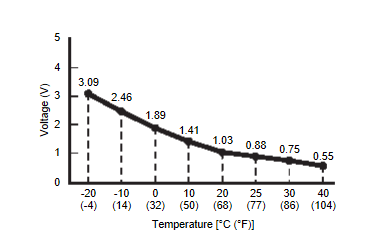
Check in-vehicle sensor. Refer to Component InspectionComponent Inspection .
. Replace A/C amp. Refer to A/C AMP. REMOVAL AND INSTALLATION
 .
. Replace in-vehicle sensor. Refer to IN-VEHICLE SENSOR REMOVAL AND INSTALLATION
 .
.
 .
.Is the inspection result normal?
 Replace A/C amp. Refer to A/C AMP. REMOVAL AND INSTALLATION
 .
. Replace in-vehicle sensor. Refer to IN-VEHICLE SENSOR REMOVAL AND INSTALLATION
 .
.5.CHECK IN-VEHICLE SENSOR POWER SUPPLY CIRCUIT FOR OPEN
- Ignition switch OFF.
- Disconnect A/C amp. connector.
- Check continuity between in-vehicle sensor harness connector and A/C amp. harness connector.
In-vehicle sensor A/C amp. Continuity Connector Terminal Connector Terminal M41 1 M55 48 Existed
Is the inspection result normal?
 Repair harness or connector.
6.CHECK IN-VEHICLE SENSOR POWER SUPPLY CIRCUIT FOR SHORT
Check voltage between in-vehicle sensor harness connector and ground.
 Replace A/C amp. Refer to A/C AMP. REMOVAL AND INSTALLATION
 .
. Repair harness or connector.
| + | - | Voltage (Approx.) | |
| In-vehicle sensor | |||
| Connector | Terminal | ||
| M41 | 1 | Ground | 0 V |
Is the inspection result normal?
 Replace A/C amp. Refer to A/C AMP. REMOVAL AND INSTALLATION
 .
. Repair harness or connector.
![[Previous]](../../../buttons/fprev.png)
![[Next]](../../../buttons/fnext.png)
