Work Procedure
- Calibration must be performed after removing/replacing the cameras, removing parts (e.g. front grille, door mirror, and others) mounted on the cameras, or replacing the around view monitor control unit.
- The use of M.U.T.-III SE is required to perform calibration or writing of calibration results to the around view monitor control unit.
- Align the white lines on the road near the vehicle at the boundary of each camera image by this camera calibration. The white lines far from the vehicle may not be aligned at the boundary of each camera image. The farther the line, the greater the difference is.
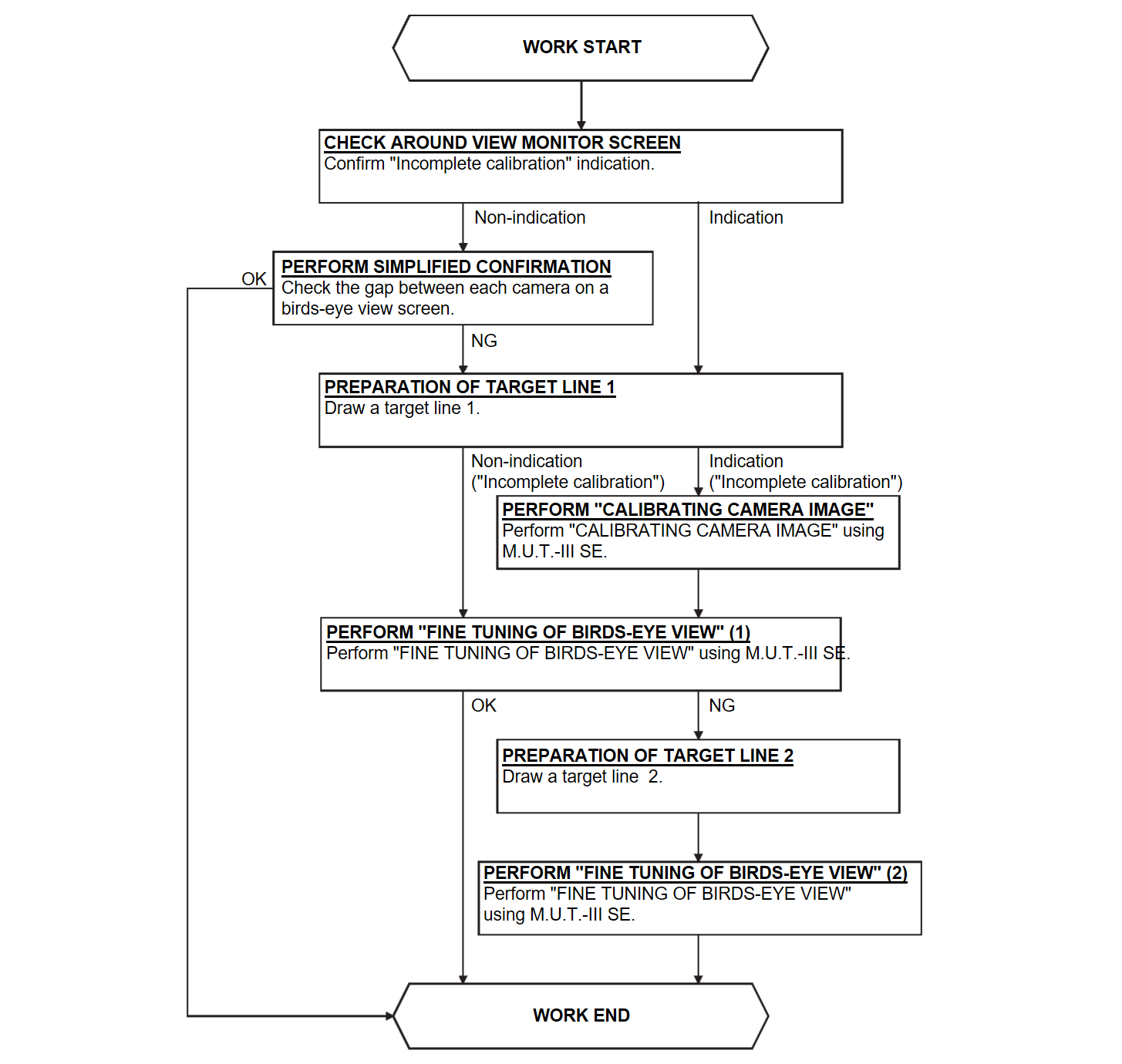
- Following the flowchart shown in the figure, perform the calibration.
| caution | When around view monitor control unit is replaced, Write the calibration data before performing this calibration. Refer to Work ProcedureDiagnosis Procedure . . |
1.CHECK AROUND VIEW MONITOR SCREEN
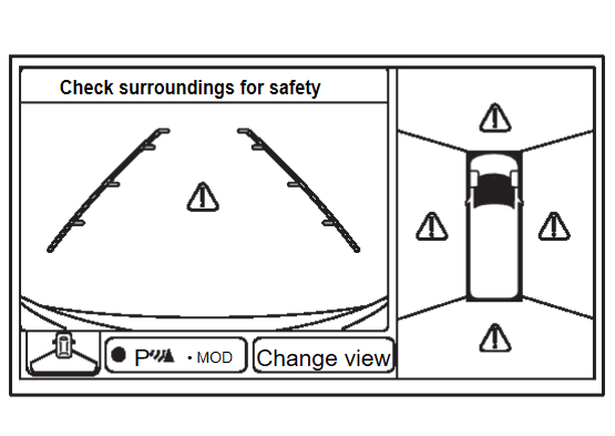
Check that there is no indication of “Incomplete calibration”.
| note | View in the incomplete calibration state is indicated by “ ” on the around view monitor. ” on the around view monitor. |
Is the “Incomplete calibration” display visible?
2.PERFORM SIMPLIFIED CONFIRMATION BY BIRDS-EYE VIEW SCREEN
Check the gap between each camera image on a birds-eye view screen. WORK END
Is the gap between each camera image exist?
 WORK END
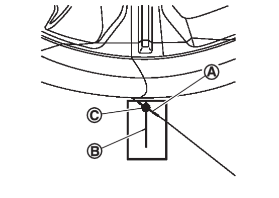
4.PREPARATION OF TARGET LINE 1
| note |
|
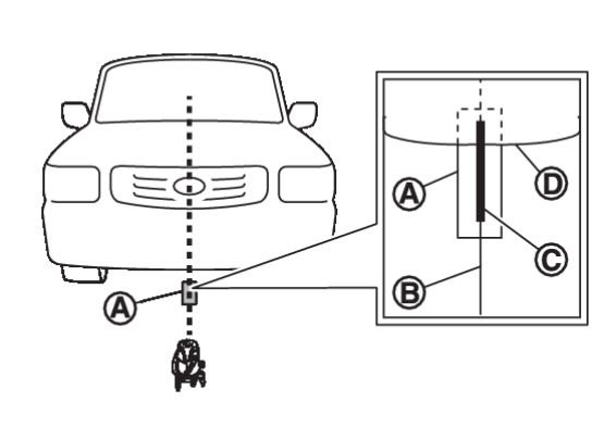
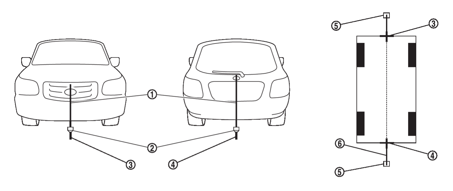
Drawing target line 1
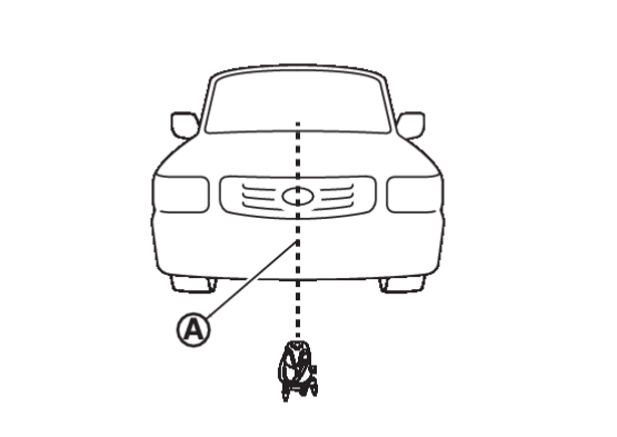
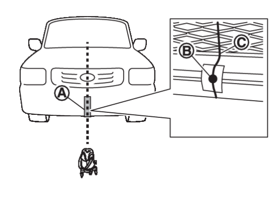
- Irradiate laser beam
 to pass throw the center of vehicle (such as center of emblem) by using Laser marker (KV9912-0000)
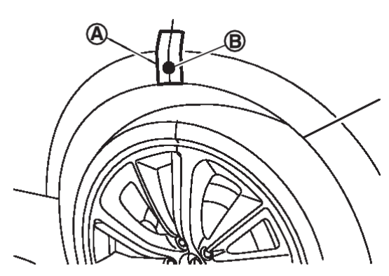
 - Put the packing tape
 on the front end of vehicle and mark the spot
  on where laser beam irradiation line passes.
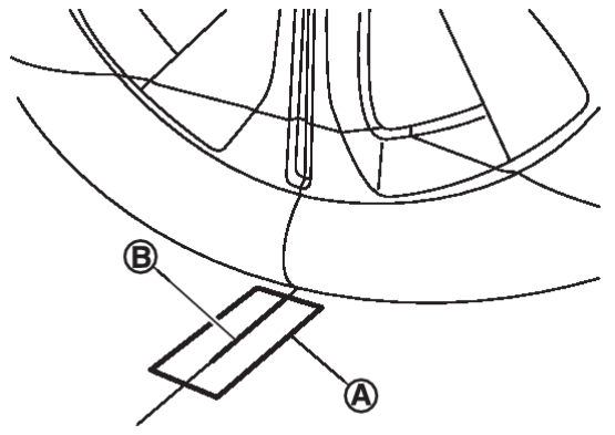
:Laser beam irradiation line. - Put packing tape
 on the ground and draw line
  along the laser beam irradiation line
  .
.
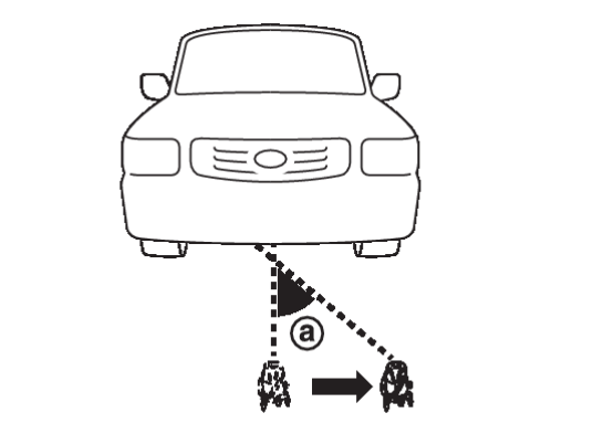
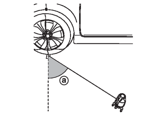
:Area around the front end of vehicle. - Slide Laser marker in 45 degree
 away.
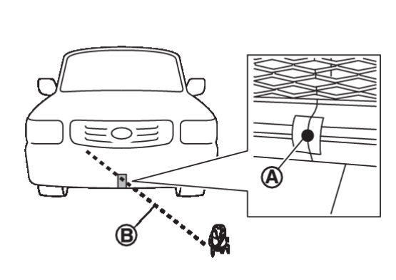
away. - Irradiate laser beam
 and adjust laser beam irradiation line to pass through the marked point
  on the front end of the vehicle.
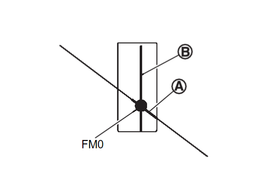
 - Draw line
 along the laser beam irradiation line which passes through the packing tape put on grand and mark FM0 where the line
  and
and  are crossed.
 - Apply the same procedure of front side to rear side and mark RM0.
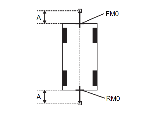
- Route the vinyl string under the vehicle, and then pull and fix it on the point approximately 1.0 m (3.28 ft) to the front and rear of the vehicle through the points FM0 and RM0 using packing tape.
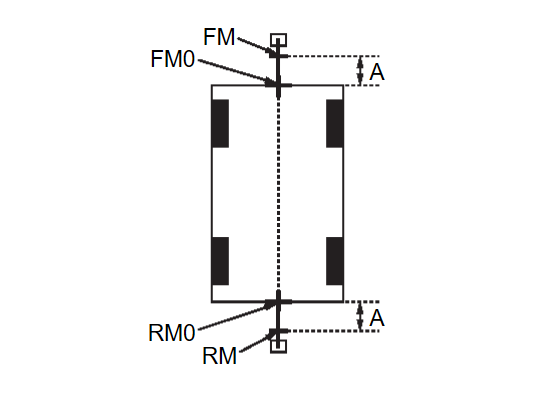
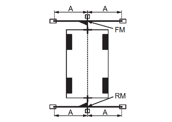
A :Approx.1.0 m (3.28 ft) - Mark the points FM and RM (mark) 75 cm (29.5 in) away from each point, FM0 and RM0.
A :Approx. 75 cm (29.5 in) - Laser marker also emits red laser from the bottom. Align the red laser with point FM and adjust the laser beam to aim the center of vehicle.
- Irradiate laser beam irradiation line
 in 90 degree from Laser marker. Route the vinyl string
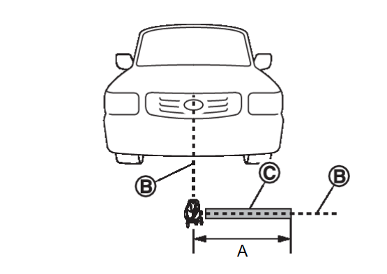
  along the laser beam irradiation line and fix it on the point approximately 1.5 m (4.92 ft)away from the point FM using packing tape.
A :Approx. 1.5 m (4.92 ft) - Rotate Laser marker to face the center line of the vehicle and rotate again in 90 degree
 . Route the vinyl string
  along the laser beam irradiation line and fix it on the point approximately 1.5 m (4.92 ft) away from the point FM using packing tape.
A :Approx. 1.5 m (4.92 ft) - Apply the same procedure of front side to rear side and fix the vinyl strings to the ground.
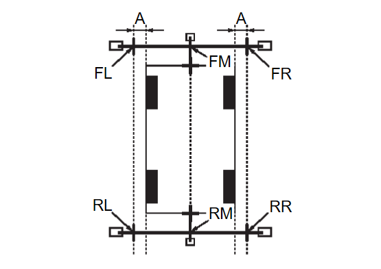
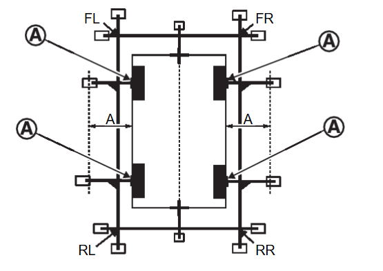
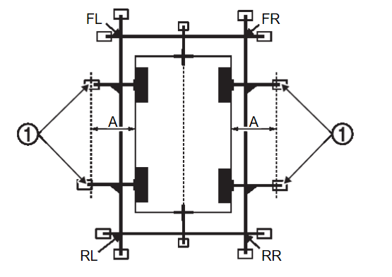
- Mark the points FL, FR, RL, and RR (mark) to both right and left [vehicle width / 2 + 30 cm (11.8in)] from the points FM and RM.
A :Approx. 30 cm (11.8 in) - Draw the lines of the points FL – RL and FR – RR with vinyl string, and fix it with packing tape.
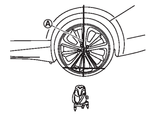
- Irradiate laser beam
 vertically from Laser marker to pass through the center of wheel.
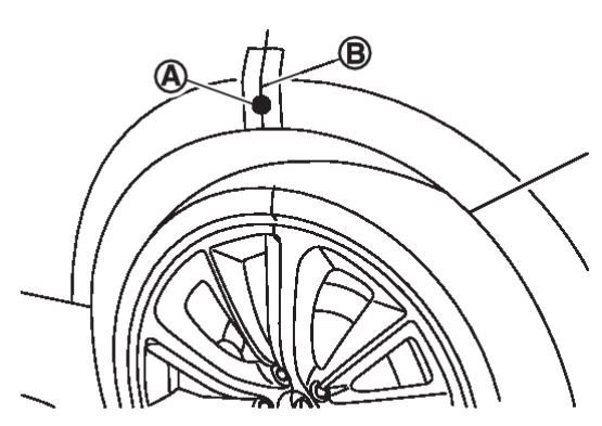
 - Put packing tape
 on fender and mark point
  on laser beam irradiation line.
 - Put packing tape
 on the ground and draw line
  along laser beam irradiation line.
 - Slide Laser marker in 45 degree away.
- Adjust the laser beam
 to pass through the marked point
  on fender.
 - Draw line
 along the laser beam irradiation line which passes through the packing tape put on grand and mark
  (the center of the axle) where the line
  and
and  are crossed.
 - Perform the same operation to rest of three wheels.
- Route the vinyl string vertically through the lines of the points FL – RL and FR – RR using a triangle scale and fix it on the point approximately 60 cm (23.6 in) away from center of axel using packing tape. Drawing target line 1 is completed.
A :Approx. 60 cm (23.6 in)
5.PERFORM “CALIBRATING CAMERA IMAGE”
 With M.U.T.-III SE
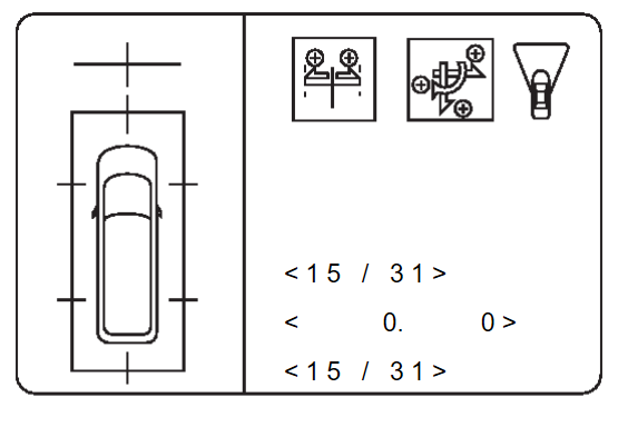
- Select “CALIBRATION” in “Special Function” mode of “Multi Around Monitor” using M.U.T.-III SE.
note In random order, perform the operation for all cameras for which un-match display  appears.
- Front camera: “CALIBRATING CAMERA IMAGE (FRONT CAMERA)”
- Side camera RH: “CALIBRATING CAMERA IMAGE (RIGHT CAMERA)”
- Side camera LH: “CALIBRATING CAMERA IMAGE (LEFT CAMERA)”
- Rear camera: “CALIBRATING CAMERA IMAGE (REAR CAMERA)”
- Perform “CALIBRATING CAMERA IMAGE (****)” as per the following procedure.
- Adjust the parameters in “AXIS X”, “AXIS Y” and “Pattern” to place the calibration marker shown on the display on the target line on the ground.
- Adjust the parameter in ”High” so that size of the target line and calibration marker are matched.
- After Status become “APPLIED”, the adjustment result is displayed on the display. If there are still gap between the target line and the calibration marker after the adjustment, adjust the parameters in “AXIS X”, “AXIS Y”, “Pattern” and “High”, and touch “Retry" for additional adjustment.
caution Never perform other operations while “PROCESSING” is displayed in Status. - Touch "OK" when “APPLIED” is displayed in Status.
- Touch “OK” button on the M.U.T.-III SE screen. Adjustment results are written to the around view monitor control unit.
caution Never perform other operations while “PROCESSING” is displayed in Status.
6.PERFORM “FINE TUNING OF BIRDS-EYE VIEW” (1)
 With M.U.T.-III SE
- Select “FINE TUNING OF BIRDS-EYE VIEW” in “Special Function” mode of “Multi Around Monitor” using M.U.T.-III SE.
- Perform “FINE TURNING OF BIRDS-EYE VIEW” as per the following procedure.
- Adjust the parameters in “AXIS X”, “AXIS Y” and “Pattern” to place the calibration marker shown on the display on the target line on the ground.
- Adjust the parameter in ”High” so that size of the target line and calibration marker are matched.
caution Perform adjustment operation slowly because approximately 1 second is required for changing image on screen. note - Touch “Next camera” to select a camera to be adjusted.
- Never perform other operations while “Switching camera” is displayed in Selected Camera.
- After Status become “APPLIED”, the adjustment result is displayed on the display. If there are still gap between the target line and the calibration marker after the adjustment, adjust the parameters in “AXIS X”, “AXIS Y”, “Pattern” and “High”, and touch “Retry" for additional adjustment.
caution Never perform other operations while “PROCESSING” is displayed in Status. - Touch "OK" when “APPLIED” is displayed in Status.
- Touch “OK” on the M.U.T.-III SE screen. Adjustment results are written to the around view monitor control unit.
caution Never perform other operations while “PROCESSING” is displayed in Status.
Is the gap between the each camera image normal?
 WORK END
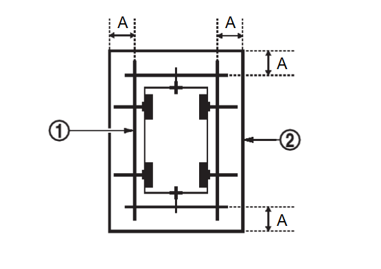
7.PREPARATION OF TARGET LINE 2
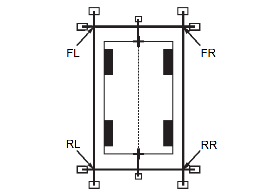
Draw target line 2  at the position of the approximately 1.0 m (39.9 in) outside from target line 1
  which established by procedure 3.
 at the position of the approximately 1.0 m (39.9 in) outside from target line 1
  which established by procedure 3.
| A | : Approx.1.0 m (39.9 in) |
| note | The white lines far from the vehicle may not be aligned at the boundary of each camera image. The farther the line, the greater the difference is. can adjust it in detail by drawing a target line 2. |
8.“PERFORM “FINE TUNING OF BIRDS-EYE VIEW” (2)
| note | This adjustment merges the boundary line of each camera image which was not able to adjust by“FINE TUNING OF BIRDS-EYE VIEW” (1). |
 With M.U.T.-III SE
- Select “FINE TUNING OF BIRDS-EYE VIEW” in “Special Function” mode of “Multi Around Monitor” using M.U.T.-III SE.
- Confirm the gap of the boundary of target line 2 between the camera image and change the parameter in “AXIS X”, “AXIS Y”, “Pattern” and “High”, and adjust the gap of the target line 2 boundary.
caution Perform adjustment operation slowly because approximately 1 second is required for changing image on screen. note - Touch “Next camera” to select a camera to be adjusted.
- Never perform other operations while “Switching camera” is displayed in Selected Camera.
- After Status become “APPLIED”, the adjustment result is displayed on the display. If there are still gap between target line 2 boundary after the adjustment, adjust the parameters in “AXIS X”, “AXIS Y”, “Pattern” and “High”, and touch “Retry" for additional adjustment.
caution Never perform other operations while “PROCESSING” is displayed in Status. - Touch "OK" when “APPLIED” is displayed in Status.
- Touch “OK” on the M.U.T.-III SE screen. Adjustment results are written to the around view monitor control unit.
caution Never perform other operations while “PROCESSING” is displayed in Status.
: WORK END
9.PREPARATION OF TARGET LINE 1
| note |
|
Preparation of target line 1
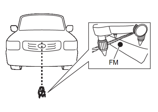
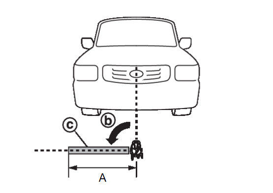
- Hang a string with a weight as shown in the figure. Put the points FM0, RM0 (mark) on the ground at the center of the vehicle front end and rear end with white packing tape or a pen.
- Route the vinyl string under the vehicle, and then pull and fix it on the point approximately 1.0 m (39.9 in) to the front and rear of the vehicle through the points FM0 and RM0 using packing tape.
A : Approx.1.0 m (39.9 in) - Put the points FM and RM (mark) 75 cm (29.5 in) from the points FM0 and RM0 individually.
A : Approx. 75 cm (29.5 in) - Route the vinyl string through the points FM and RM using a triangle scale, and then fix it at approximately 1.5 m (59.0 in) on both sides with packing tape.
A Approx. 1.5 m (59.0 in) - Put the points FL, FR, RL, and RR (mark) to both right and left [vehicle width / 2 + 30 cm (11.8 in)] from the points FM and RM.
A : Approx. 30 cm (11.8 in) - Draw the lines of the points FL – RL and FR – RR with vinyl string, and fix it with packing tape.
- Put a mark on the center of each axle
 , draw vertical lines to the lines of the points FL – RL and FR – RR from the marks on the center of the axle using a triangle scale, and then fix the lines using packing tape.
A : Approx. 60 cm (23.6 in)
10.PERFORM “CALIBRATING CAMERA IMAGE”
 With M.U.T.-III SE
- Select “CALIBRATION” in “Special Function” mode of “Multi Around Monitor” using M.U.T.-III SE.
note In random order, perform the operation for all cameras for which un-match display  appears.
- Front camera: “CALIBRATING CAMERA IMAGE (FRONT CAMERA)”
- Side camera RH: “CALIBRATING CAMERA IMAGE (RIGHT CAMERA)”
- Side camera LH: “CALIBRATING CAMERA IMAGE (LEFT CAMERA)”
- Rear camera: “CALIBRATING CAMERA IMAGE (REAR CAMERA)”
- Perform “CALIBRATING CAMERA IMAGE (****)” as per the following procedure.
- Adjust the parameters in “AXIS X”, “AXIS Y” and “Pattern” to place the calibration marker shown on the display on the target line on the ground.
- Adjust the parameter in ”High” so that size of the target line and calibration marker are matched.
- After Status become “APPLIED”, the adjustment result is displayed on the display. If there are still gap between the target line and the calibration marker after the adjustment, adjust the parameters in “AXIS X”, “AXIS Y”, “Pattern” and “High”, and touch “Retry" for additional adjustment.
caution Never perform other operations while “PROCESSING” is displayed in Status. - Touch "OK" when “APPLIED” is displayed in Status.
- Touch “OK” on the M.U.T.-III SE screen. Adjustment results are written to the around view monitor control unit.
caution Never perform other operations while “PROCESSING” is displayed in Status.
11.PERFORM “FINE TUNING OF BIRDS-EYE VIEW” (1)
 With M.U.T.-III SE
- Select “FINE TUNING OF BIRDS-EYE VIEW” in “Special Function” mode of “Multi Around Monitor” using M.U.T.-III SE.
- Perform “FINE TURNING OF BIRDS-EYE VIEW” as per the following procedure.
- Adjust the parameters in “AXIS X”, “AXIS Y” and “Pattern” to place the calibration marker shown on the display on the target line on the ground.
- Adjust the parameter in ”High” so that size of the target line and calibration marker are matched.
caution Perform adjustment operation slowly because approximately 1 second is required for changing image on screen. note - Touch “Next camera” to select a camera to be adjusted.
- Never perform other operations while “Switching camera” is displayed in Selected Camera.
- After Status become “APPLIED”, the adjustment result is displayed on the display. If there are still gap between the target line and the calibration marker after the adjustment, adjust the parameters in “AXIS X”, “AXIS Y”, “Pattern” and “High”, and touch “Retry" for additional adjustment.
caution Never perform other operations while “PROCESSING” is displayed in Status. - Touch "OK" when “APPLIED” is displayed in Status.
- Touch “OK” on the M.U.T.-III SE screen. Adjustment results are written to the around view monitor control unit.
caution Never perform other operations while “PROCESSING” is displayed in Status.
Is the gap between the each camera image normal?
 WORK END
12.PREPARATION OF TARGET LINE 2
Draw target line 2  at the position of the approximately 1.0 m (39.9 in) outside from target line 1
  which established by procedure 2.
 at the position of the approximately 1.0 m (39.9 in) outside from target line 1
  which established by procedure 2.
| A | : Approx.1.0 m (39.9 in) |
| note | The white lines far from the vehicle may not be aligned at the boundary of each camera image. The farther the line, the greater the difference is. can adjust it in detail by drawing a target line 2. |
13.“PERFORM “FINE TUNING OF BIRDS-EYE VIEW” (2)
| note | This adjustment merges the boundary line of each camera image which was not able to adjust by “FINE TUNING OF BIRDS-EYE VIEW” (1). |
 With M.U.T.-III SE
- Select “FINE TUNING OF BIRDS-EYE VIEW” in “Special Function” mode of “Multi Around Monitor” using M.U.T.-III SE.
- Confirm the gap of the boundary of target line 2 between the camera image and change the parameter in “AXIS X”, “AXIS Y”, “Pattern” and “High”, and adjust the gap of the target line 2 boundary.
caution Perform adjustment operation slowly because approximately 1 second is required for changing image on screen. note - Touch “Next camera” to select a camera to be adjusted.
- Never perform other operations while “Switching camera” is displayed in Selected Camera.
- After Status become “APPLIED”, the adjustment result is displayed on the display. If there are still gap between target line 2 boundary after the adjustment, adjust the parameters in “AXIS X”, “AXIS Y”, “Pattern” and “High”, and touch “Retry" for additional adjustment.
caution Never perform other operations while “PROCESSING” is displayed in Status. - Touch "OK" when “APPLIED” is displayed in Status.
- Touch “OK” on the M.U.T.-III SE screen. Adjustment results are written to the around view monitor control unit.
caution Never perform other operations while “PROCESSING” is displayed in Status.
: WORK END
![[Previous]](../../../buttons/fprev.png)
![[Next]](../../../buttons/fnext.png)
