System Description
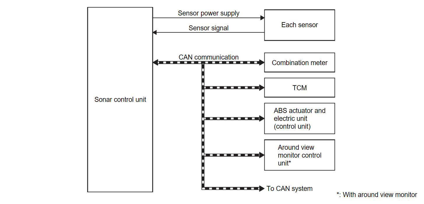
SYSTEM DIAGRAM
| Part name | Description |
| Sonar control unit | Sonar Control Unit |
| Each sensor | Sonar Sensor |
| Combination meter |
|
| TCM | Transmits shift position signal to the sonar control unit via CAN communication. |
| ABS actuator and electric unit (control unit) | Transmits the vehicle speed signal to the sonar control unit via CAN communication. |
| Around view monitor control unit | Receiving a sonar indicator signal via CAN communication. |
Sonar Control Unit Input Signal (CAN Communication)
| Transmit unit | Signal name |
| Combination meter | System setting signal |
| ABS actuator and electric unit (control unit) | Vehicle speed signal |
| TCM | Shift position signal |
Sonar Control Unit Output Signal (CAN Communication)
| Transmit unit | Signal name |
| Combination meter |
|
| Around view monitor control unit* | Sonar indicator signal |
*: With around view monitor
DESCRIPTION
- The sonar sensor installed to the front bumper and the rear bumper detects obstacles around the bumper.
- The sonar control unit changes the buzzer cycle and the warning of the sonar indicator (combination meter and around view monitor control unit), according to a distance from an obstacle detected by the sonar sensor.
- The sonar control unit controls the buzzer cycle according to a buzzer output signal transmitted to the combination meter and the around view monitor control unit via CAN communication.
- The sonar control unit controls the sonar indicator according to a sonar indicator display signal transmitted to the combination meter and the around view monitor control unit via CAN communication.
SONAR SYSTEM ACTIVATION CONDITION
The sonar system warns the driver of the presence or absence of obstacles by buzzer and the sonar indicator when the following conditions are satisfied while the ignition switch is turned ON.
Models without Side Sensor
×: Activation
| Shift position | Vehicle speed (Approx.) | Obstacle detecting sensor | Buzzer | Sonar indicator |
| R | 10 km/h (6.21MPH) or less | Front sensor | × | × |
| Rear sensor | × | × | ||
| D | 10 km/h (6.21MPH) or less | Front sensor | × | × |
| Rear sensor | — | — |
Models with Side Sensor
×: Activation
| Shift position | Vehicle speed (Approx.) | Obstacle detecting sensor | Buzzer | Sonar indicator |
| R | 10 km/h (6.21MPH) or less | Front sensor | — | × |
| Rear sensor | × | × | ||
| D | 10 km/h (6.21MPH) or less | Front sensor | × | × |
| Rear sensor | — | — |
| note | The following items can be set for the sonar system on the settings screen of the combination meter.
|
OBSTACLE DETECTION DISTANCE
The sonar control unit changes a buzzer cycle and a sonar indicator indication according to a distance from an obstacle.
Warning Buzzer Frequency
- The warning buzzer output frequency changes 4 levels according to the detection distance.
- As the vehicle approaches an obstacle, the buzzer-sounding cycle becomes shorter.
- The nearest sensor from the detected obstacle applies the buzzer output frequency if plural sensors detect any obstacle simultaneously.
| note | Buzzer stops when the vehicle moves away from an obstacle and the warning level decreases. |
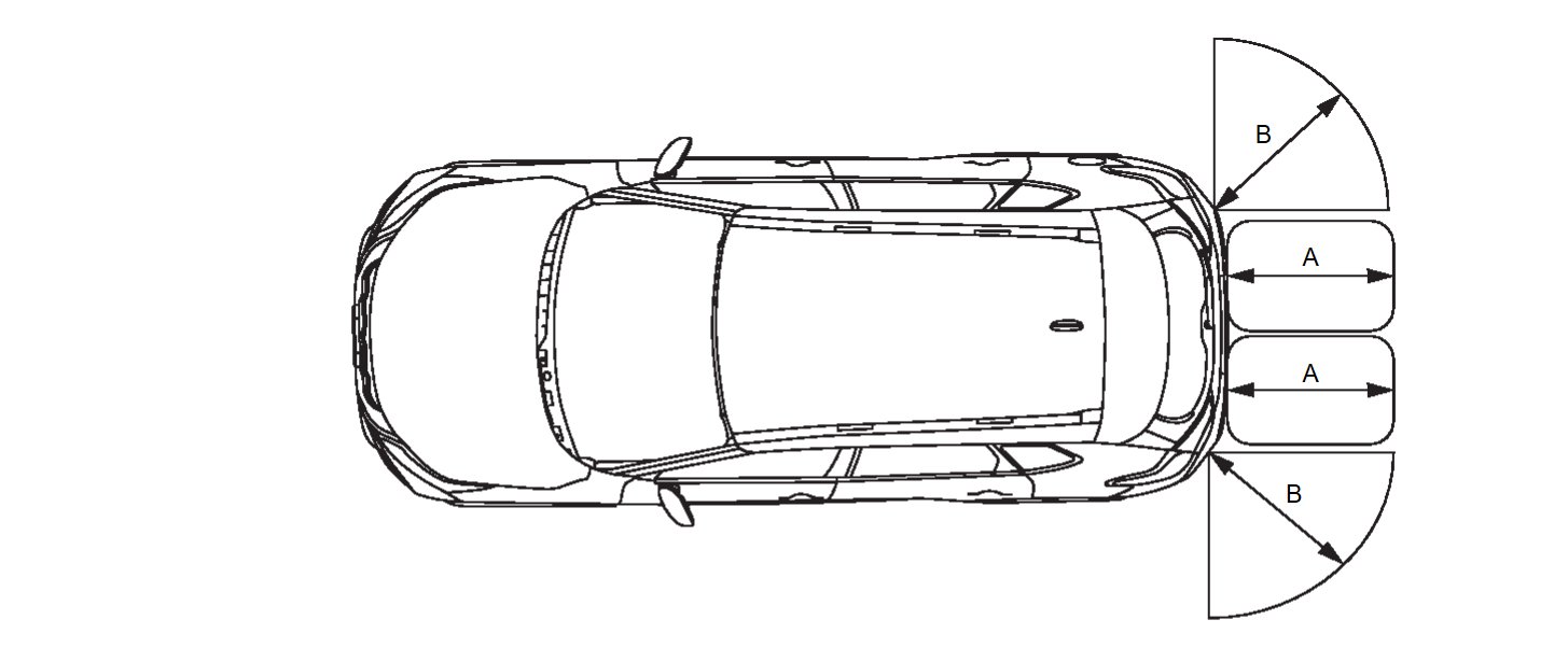
- 4 Sensor Models
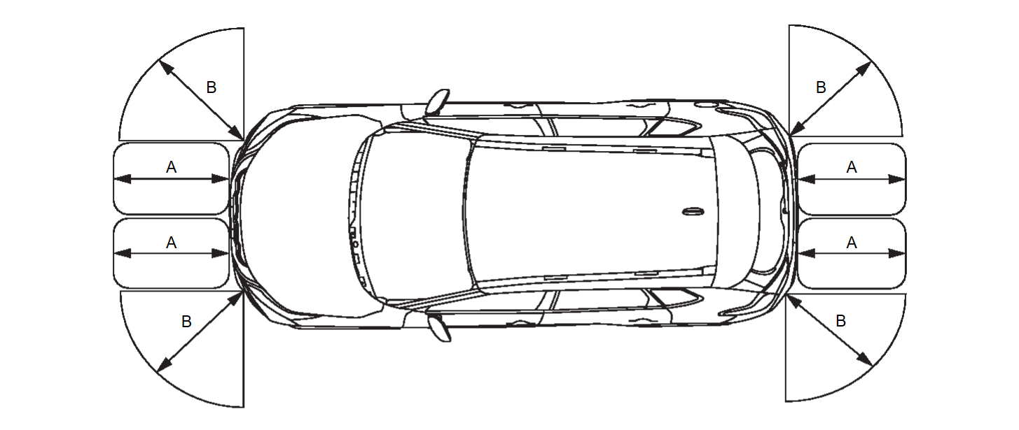
- 8 Sensor Models
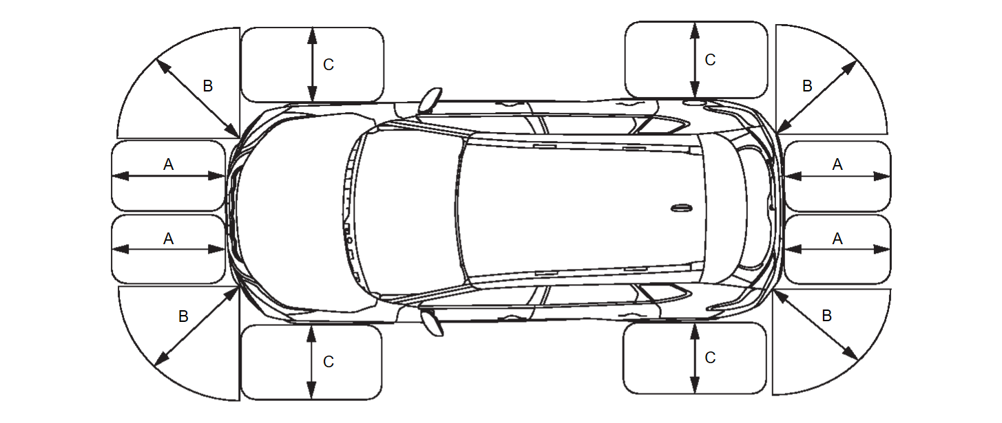
- 12 Sensor Models
Detection distance (default value)
| Detection distance | Warning buzzer frequency |
| 30 - 35 cm (11.81 - 13.78 in) | 10.0 Hz |
| 35 - 50 cm (13.78 - 19.69 in) | 9.0 Hz |
| 50 - 70 cm (19.69 - 27.56 in) | 6.66 Hz |
| 70 - 90 cm (27.56 - 35.43 in) | 5.0 Hz |
| 90 - 120 cm (35.43 - 47.24 in) | 4.0 Hz |
| 120 - 150 cm (47.24 - 59.06 in) | 3.0 Hz |
| 150 - 180 cm (59.06 - 70.87 in) | 2.5 Hz |
| 180 cm or more (70.87 in or more) | 2.0 Hz |
- Detection distance of an obstacle changes, as shown in the table below, when the detection sensitivity is changed on the settings screen of the information display of the combination meter.Detection distance
Item (detection range) Corner sensor Side sensor Front center sensor Rear center sensor FAR Approx. 66 cm (25.98 in) Approx. 66 cm (25.98 in) Approx. 110 cm (43.31 in) Approx. 165 cm (64.96 in) NORMAL (default value) Approx. 60 cm (23.62 in) Approx. 60 cm (23.62 in) Approx. 100 cm (39.37 in) Approx. 150 cm (59.06 in) NEAR Approx. 54 cm (21.26 in) Approx. 54 cm (21.26 in) Approx. 90 cm (35.43 in) Approx. 135 cm (53.51 in)
Sonar Indicator
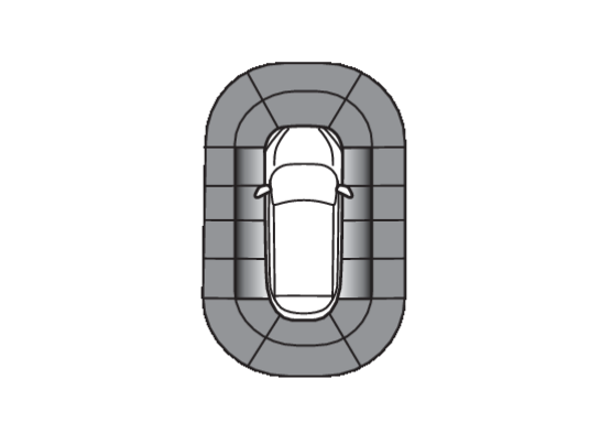
- The sonar control unit displays a warning on sonar indicator in three stages (green, yellow, and red), according to a distance from an obstacle.
note - A distance from an obstacle is also displayed on the information display of the combination meter.
- Sonar indicator is displayed also on Bird-Eye view and front-side view screen of around view monitor.
- Warning displayed on the sonar indicator and a distance change according to a distance between an obstacle and sensor as shown in the following table.
Status of warning Detection distance Corner sensor Front center sensor Rear center sensor Red 0 - 30 cm (0 - 11.81 in)0 - 30 cm (0 - 11.81 in)0 - 30 cm (0 - 11.81 in)Yellow 31 - 50 cm (12.2 - 19.69 in)31 - 50 cm (12.2 - 19.69 in)31 - 60 cm (12.2 - 23.62 in)Green 51 - 60 cm (20.08 - 23.62 in)51 - 80 cm (20.08 - 31.49 in)61 - 130 cm (24.02 - 51.18 in)
MAC(Message Authentication Code)
MAC (Message Authentication Code) is a function that prevents unauthorized communication from other than the ECU with MAC function by secure authentication communication. Sonar control unit can write a MAC key required for communication between the ECUs and perform MAC diagnosis.
![[Previous]](../../../buttons/fprev.png)
![[Next]](../../../buttons/fnext.png)
