System Description
SYSTEM DIAGRAM
| Component | Function |
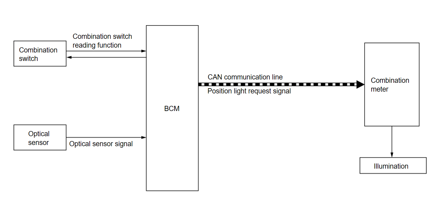
| Combination switch | Inputs the each switch condition signal to BCM. |
| Optical sensor | The optical sensor outputs voltage signals to the BCM according to the brightness of the ambient light. |
| BCM |
|
| Combination meter | Turns ON/OFF the illuminations according to the request from BCM. |
OUTLINE
Each illumination is controlled by each function of BCM and combination meter.
Control by BCM
- Parking, license plate, side marker and tail light control function
- Combination switch reading function
- Auto light function
Control by combination meter
- Illumination control function
ILLUMINATION CONTROL
- BCM detect combination switch condition by the combination switch reading function.
- BCM transmits position light request signal to combination meter according to tail light ON condition. Refer to System Description
 .
. - Combination meter enters in the nighttime mode according to position light request signal and provides the power supply to each illumination.
![[Previous]](../../../buttons/fprev.png)
![[Next]](../../../buttons/fnext.png)
