System Description
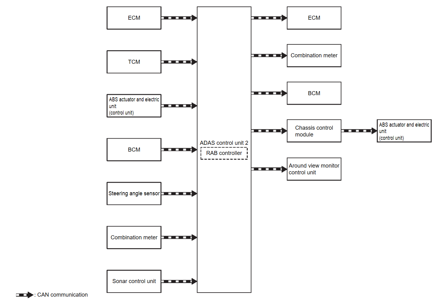
SYSTEM DIAGRAM
| Component | Function |
| ECM | ECM |
| TCM | TCM |
| ABS actuator and electric unit (control unit) | ABS Actuator and Electric Unit (Control Unit) |
| Chassis control module | Chassis Control Module |
| BCM | System Description |
| Steering angle sensor | Steering Angle Sensor |
| Combination meter (FULL TFT METER) | Combination Meter |
| Combination meter (7 INCH INFORMATION DISPLAY) | Combination Meter |
| Sonar control unit | Sonar Control Unit |
| Around view monitor control unit | Around View Monitor Control Unit |
| ADAS control unit 2 | ADAS Control Unit 2 |
ADAS CONTROL UNIT 2 INPUT/OUTPUT SIGNAL ITEM
Input Signal Item
| Transmit unit | Signal name | Description | |
| ECM | CAN communication | Closed throttle position signal | Receives idle position state (ON/OFF) |
| Accelerator pedal position signal | Receives accelerator pedal position (angle) | ||
| Engine speed signal | Receives engine speed | ||
| TCM | CAN communication | Input speed signal | Receives the number of revolutions of input shaft |
| Current gear position signal | Receives a current gear position | ||
| Shift position signal | Receives a selector lever position | ||
| Output shaft revolution signal | Receives the number of revolutions of output shaft | ||
| ABS actuator and electric unit (control unit) | CAN communication | ABS malfunction signal | Receives a malfunction state of ABS |
| TCS malfunction signal | Receives a malfunction state of TCS | ||
| ASC malfunction signal | Receives a malfunction state of ASC | ||
| Vehicle speed signal (ABS) | Receives wheel speeds of four wheels | ||
| Brake fluid pressure signal | Receives brake fluid pressure | ||
| BCM | CAN communication | Stop light switch signal | Receives an operational state of the brake pedal |
| Steering angle sensor | CAN communication | Steering angle sensor signal | Receives the number of revolutions, turning direction of the steering wheel |
| Combination meter | CAN communication | System selection signal | Receives a selection state of each item selected with the combination meter |
| Sonar control unit | CAN communication | Sonar sensor signal | Receives obstacle information (existence & distance) |
Output Signal Item
| Reception unit | Signal name | Description | |
| ECM | CAN communication | Wheel torque request signal | Transmits a signal to control the engine torque |
| Combination meter | CAN communication | Meter display signal | Transmits a signal to display a state of the system on the information display |
| Buzzer output signal | Transmits a signal to activate buzzer | ||
| RAB warning light signal |
| ||
| BCM | CAN communication | Stop light request signal | Transmits a signal to activates the stop light |
| ABS actuator and electric unit (control unit) (via chassis control module) | CAN communication | Brake fluid pressure control signal | Transmits a brake fluid pressure control signal to activates the brake |
| Around view monitor control unit | CAN communication | RAB warning signal | Transmits a RAB warning signal to appear the red frame in the center display |
FUNCTION DESCRIPTION
- The Rear Automatic Braking system can assist the driver when the vehicle is backing up and approaching objects directly behind the vehicle.
- When the shift lever is in the R (Reverse) position and the vehicle speed is less than approximately 15 km/h (7 MPH), the RAB system operates.
- The RAB system detects obstacles behind the vehicle using the sonar sensors.
- If a risk of a collision with an obstacle is detected when own vehicle is backing up, the RAB system warning indicator blinks in the vehicle information display, a red frame appears in the center display (with Multi Around Monitor system), and the system chimes three times.
- The system automatically applies the brakes.
note - After the automatic brake application, the driver must depress the brake pedal to maintain brake pressure.
- Driver can temporarily cancel the sonar function in the vehicle, but the RAB system continues to operate.
OPERATION DESCRIPTION
- Sonar detects a object approaching, and transmits the object detection signal to ADAS control unit 2 via CAN communication.
- The ADAS control unit 2 performs the following operations according to the degree of possibility of a collision.
- Transmits the buzzer output signal to the combination meter and sounds the buzzer.
- Transmits the meter display signal to the combination meter and displays the RAB system warning indicator.
- Transmits the brake fluid pressure control signal to the ABS actuator and electric unit (control unit) and performs the brake control.
- Transmits the stop light request signal to BCM and turn ON the stop light.
| note |
|
OPERATION CONDITION
ADAS control unit 2 performs the control when the following conditions are satisfied.
- RAB system: ON
- Vehicle speed: Less than approximately 15 km/h (9 MPH)
- When there is a possibility of a collision with the object backward.
CANCEL CONDITION
The ADAS control unit 2 cancels the operation when the system is under any conditions of the operation cancellation condition.
- When the system judges that the vehicle comes to a standstill by the system control.
- When the system malfunction occurs.
- When the sonar area of the rear bumper is dirty and the measurement of the distance between the object becomes difficult.
![[Previous]](../../../buttons/fprev.png)
![[Next]](../../../buttons/fnext.png)

