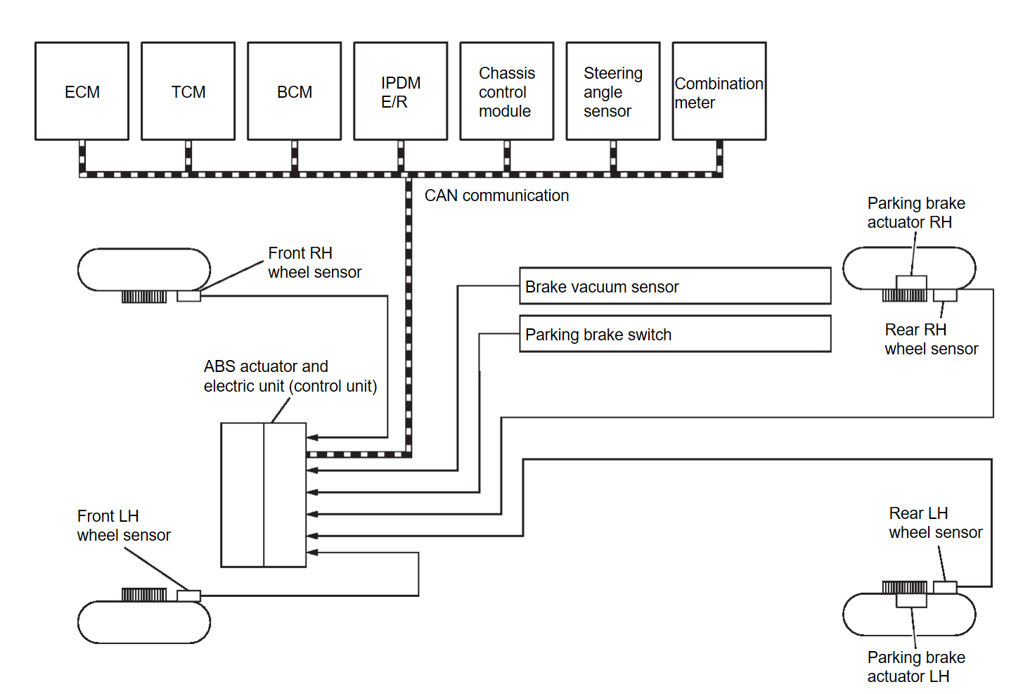
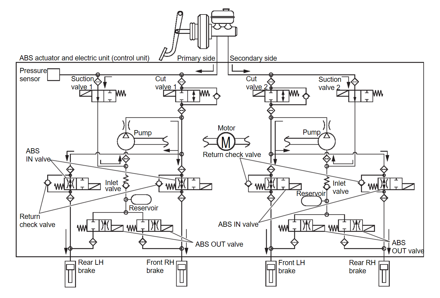
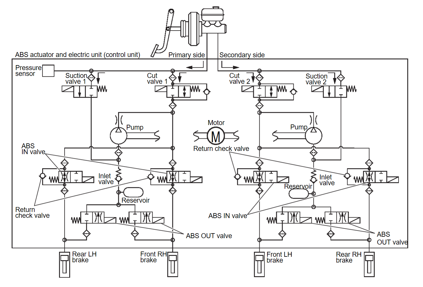
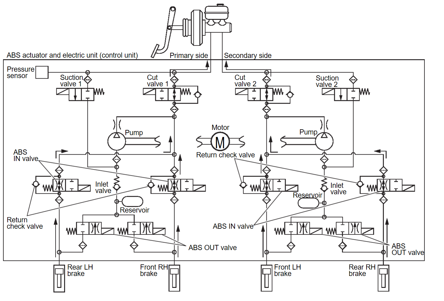
System Description
- The system switches fluid pressure of each brake to increase, to hold or to decrease according to signals from control unit in ABS actuator and electric unit (control unit). This control system is applied to ASC function, TCS function, ABS function, EBD function, brake limited slip differential (BLSD) function, brake assist function, brake force distribution function, and hill start assist function.
- Fail-safe function is available for each function and is activated by each function when system malfunction occurs.
INPUT SIGNAL AND OUTPUT SIGNAL
Major signal transmission between each unit via communication lines is shown in the following table.
| Component parts | Signal description |
| ABS actuator and electric unit (control unit) | ABS Actuator and Electric Unit (Control Unit) |
| Front LH wheel sensor | Wheel Sensor and Sensor Rotor |
| Front RH wheel sensor | Wheel Sensor and Sensor Rotor |
| Rear LH wheel sensor | Wheel Sensor and Sensor Rotor |
| Rear RH wheel sensor | Wheel Sensor and Sensor Rotor |
| Brake vacuum sensor | Brake Vacuum Sensor |
| Parking brake switch | Parking Brake Switch |
| Parking brake actuator (LH) | Parking Brake Actuator |
| Parking brake actuator (RH) | Parking Brake Actuator |
| ECM | Mainly transmits the following signals to ABS actuator and electric unit (control unit) via CAN communication.
|
| TCM | Mainly transmits the following signals to ABS actuator and electric unit (control unit) via CAN communication.
|
| BCM | Mainly transmits the following signals to ABS actuator and electric unit (control unit) via CAN communication.
Mainly receives the following signals from ABS actuator and electric unit (control unit) via CAN communication.
|
| IPDM E/R | Mainly transmits the following signals to ABS actuator and electric unit (control unit) via CAN communication.
|
| Chassis control module | Mainly transmits the following signals to ABS actuator and electric unit (control unit) via CAN communication.
|
| Steering angle sensor | Mainly transmits the following signals to ABS actuator and electric unit (control unit) via CAN communication.
|
| Combination meter | Mainly transmits the following signals to ABS actuator and electric unit (control unit) via CAN communication.
Mainly receives the following signals from ABS actuator and electric unit (control unit) via CAN communication.
|
VALVE OPERATION [ASC FUNCTION, TCS FUNCTION, BRAKE LIMITED SLIP DIFFERENTIAL (BLSD) FUNCTION, BRAKE ASSIST FUNCTION, BRAKE FORCE DISTRIBUTION FUNCTION, hill start assist FUNCTION
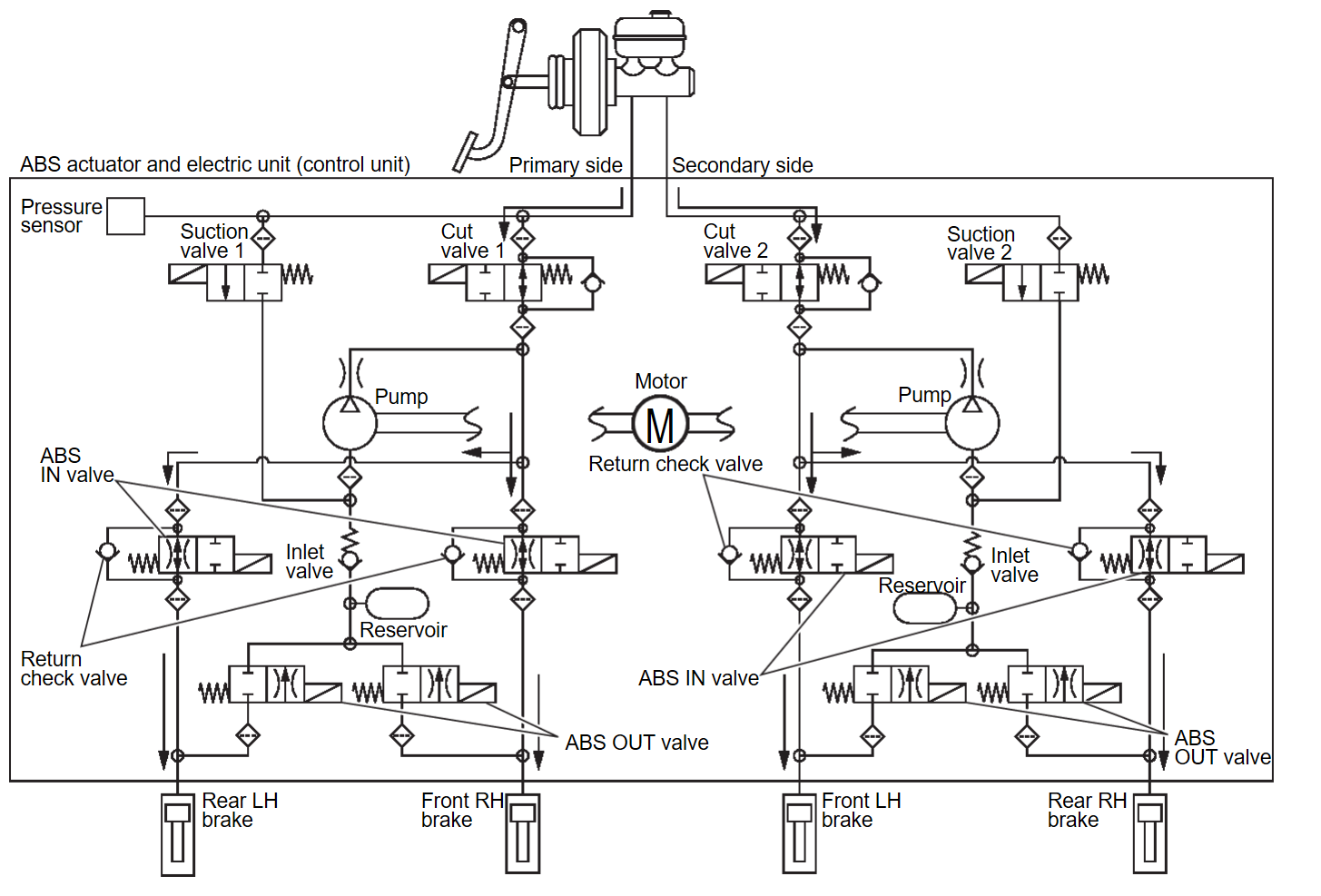
Each valve is operated and fluid pressure of brake is controlled.
ASC Function, TCS Function, Brake Limited Slip Differential (BLSD) Function, Brake Assist Function, Brake force distribution Function, and hill start assist Function are in Operation (During Pressure Increases)
| Component parts | Not activated | When pressure increases |
| Cut valve 1 | Power supply is not supplied (open) | Power supply is supplied (close) |
| Cut valve 2 | Power supply is not supplied (open) | Power supply is supplied (close) |
| Suction valve 1 | Power supply is not supplied (close) | Power supply is supplied (open) |
| Suction valve 2 | Power supply is not supplied (close) | Power supply is supplied (open) |
| ABS IN valve | Power supply is not supplied (open) | Power supply is not supplied (open) |
| ABS OUT valve | Power supply is not supplied (close) | Power supply is not supplied (close) |
| Each brake (fluid pressure) | — | Pressure increases |
During pressure front RH brake increases
- Brake fluid is conveyed to the pump from the master cylinder through suction valve 1 and is pressurized by the pump operation. The pressurized brake fluid is supplied to the front RH brake through the ABS IN valve. For the left brake, brake fluid pressure is maintained because the pressurization is unnecessary. The pressurization for the left brake is controlled separately from the right brake.
During pressure front LH brake increases
- Brake fluid is conveyed to the pump from the master cylinder through suction valve 2 and is pressurized by the pump operation. The pressurized brake fluid is supplied to the front LH brake through the ABS IN valve. For the right brake, brake fluid pressure is maintained because the pressurization is unnecessary. The pressurization for the right brake is controlled separately from the left brake.
During pressure rear RH brake increases
- Brake fluid is conveyed to the pump from the master cylinder through suction valve 2 and is pressurized by the pump operation. The pressurized brake fluid is supplied to the rear RH brake through the ABS IN valve. For the left brake, brake fluid pressure is maintained because the pressurization is unnecessary. The pressurization for the left brake is controlled separately from the right brake.
During pressure rear LH brake increases
- Brake fluid is conveyed to the pump from the master cylinder through suction valve 1 and is pressurized by the pump operation. The pressurized brake fluid is supplied to the rear LH brake through the ABS IN valve. For the right brake, brake fluid pressure is maintained because the pressurization is unnecessary. The pressurization for the right brake is controlled separately from the left brake.
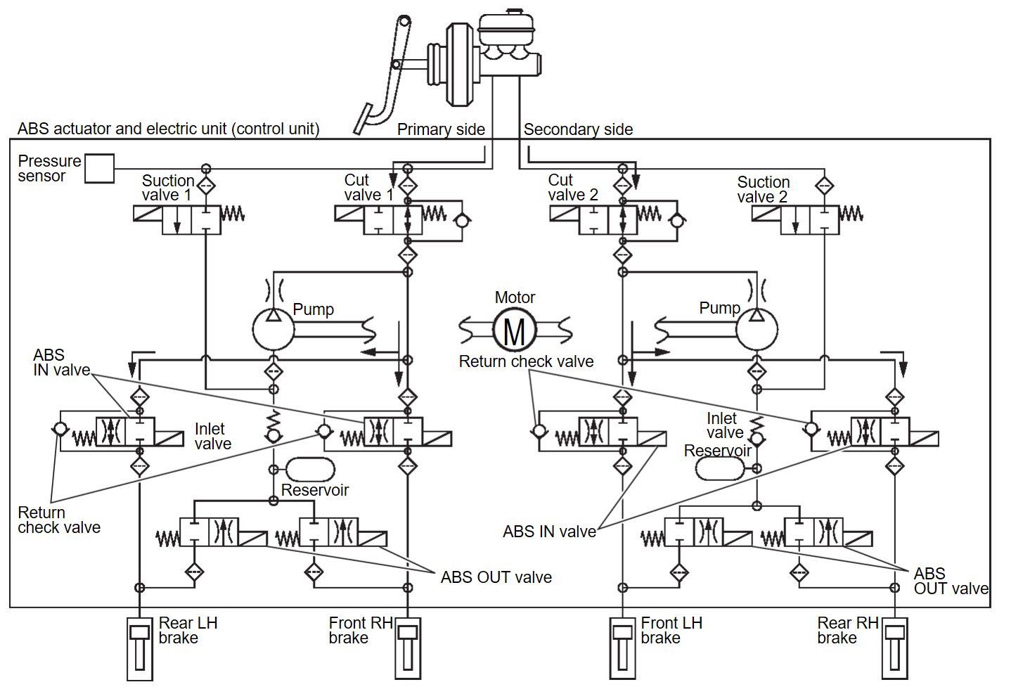
ASC Function, TCS Function, Brake Limited Slip Differential (BLSD) Function, Brake Assist Function, Brake force distribution Function, and hill start assist Function are in Operation (During Pressure Holds)
| Component parts | Not activated | When pressure holds |
| Cut valve 1 | Power supply is not supplied (open) | Power supply is supplied (close) |
| Cut valve 2 | Power supply is not supplied (open) | Power supply is supplied (close) |
| Suction valve 1 | Power supply is not supplied (close) | Power supply is not supplied (close) |
| Suction valve 2 | Power supply is not supplied (close) | Power supply is not supplied (close) |
| ABS IN valve | Power supply is not supplied (open) | Power supply is not supplied (open) |
| ABS OUT valve | Power supply is not supplied (close) | Power supply is not supplied (close) |
| Each brake (fluid pressure) | — | Pressure holds |
During pressure front RH brake holds
- Since the cut valve 1 and the suction valve 1 are closed, the front RH brake, master cylinder, and reservoir are blocked. This maintains fluid pressure applied on the front RH brake. The pressurization for the left brake is controlled separately from the right brake.
During pressure front LH brake holds
- Since the cut valve 2 and the suction valve 2 are closed, the front LH brake, master cylinder, and reservoir are blocked. This maintains fluid pressure applied on the front LH brake. The pressurization for the right brake is controlled separately from the left brake.
During pressure rear RH brake holds
- Since the cut valve 2 and the suction valve 2 are closed, the rear RH brake, master cylinder, and reservoir are blocked. This maintains fluid pressure applied on the rear RH brake. The pressurization for the left brake is controlled separately from the right brake.
During pressure rear LH brake holds
- Since the cut valve 1 and the suction valve 1 are closed, the rear LH brake, master cylinder, and reservoir are blocked. This maintains fluid pressure applied on the rear LH brake. The pressurization for the right brake is controlled separately from the left brake.
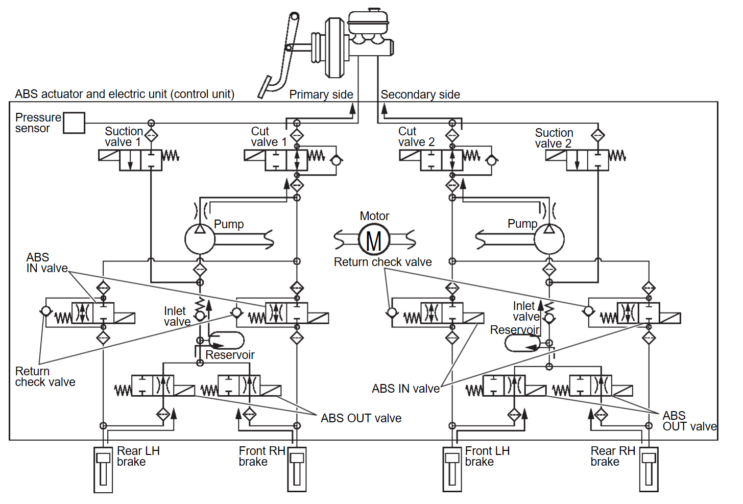
ASC Function, TCS Function, Brake Limited Slip Differential (BLSD) Function, Brake Assist Function, Brake force distribution Function, and hill start assist Function are in Operation (During Pressure Decrease)
| Component parts | Not activated | When pressure decrease |
| Cut valve 1 | Power supply is not supplied (open) | Power supply is not supplied (open) |
| Cut valve 2 | Power supply is not supplied (open) | Power supply is not supplied (open) |
| Suction valve 1 | Power supply is not supplied (close) | Power supply is not supplied (close) |
| Suction valve 2 | Power supply is not supplied (close) | Power supply is not supplied (close) |
| ABS IN valve | Power supply is not supplied (open) | Power supply is not supplied (open) |
| ABS OUT valve | Power supply is not supplied (close) | Power supply is not supplied (close) |
| Each brake (fluid pressure) | — | Pressure decreases |
During pressure front RH brake decreased
- Since the suction valve 1 and the ABS OUT valve close and the cut valve 1 and the ABS IN valve open, the fluid pressure applied on the front RH brake is reduced by supplying the fluid pressure to the master cylinder via the ABS IN valve and the cut valve 1. The pressurization for the right brake is controlled separately from the left brake.
During pressure front LH brake decreased
- Since the suction valve 2 and the ABS OUT valve close and the cut valve 2 and the ABS IN valve open, the fluid pressure applied on the front LH brake is reduced by supplying the fluid pressure to the master cylinder via the ABS IN valve and the cut valve 2. The pressurization for the left brake is controlled separately from the right brake.
During pressure rear RH brake decreased
- Since the suction valve 2 and the ABS OUT valve close and the cut valve 2 and the ABS IN valve open, the fluid pressure applied on the rear RH brake is reduced by supplying the fluid pressure to the master cylinder via the ABS IN valve and the cut valve 2. The pressurization for the right brake is controlled separately from the left brake.
During pressure rear LH brake decreased
- Since the suction valve 1 and the ABS OUT valve close and the cut valve 1 and the ABS IN valve open, the fluid pressure applied on the rear LH brake is reduced by supplying the fluid pressure to the master cylinder via the ABS IN valve and the cut valve 1. The pressurization for the left brake is controlled separately from the right brake.
Component Parts and Function
| Component parts | Function |
| Pump |
|
| Motor | Activates the pump according to signals from ABS actuator and electric unit (control unit). |
| Cut valve 1 Cut valve 2 | Shuts off the ordinary brake line from master cylinder. |
| Suction valve 1 Suction valve 2 | Supplies the brake fluid from master cylinder to the pump. |
| ABS IN valve | Switches the fluid pressure line to increase or hold according. |
| ABS OUT valve | Switches the fluid pressure line to increase, hold or decrease according. |
| return check valve | Returns the brake fluid from each brake to master cylinder by bypassing orifice of each valve when brake is released. |
| Reservoir | Temporarily reserves the brake fluid drained from each brake, so that pressure efficiently decreases when decreasing pressure of each brake. |
| Pressure sensor | Detects the brake fluid pressure and transmits signal to ABS actuator and electric unit (control unit). |
VALVE OPERATION (ABS FUNCTION)
Each valve is operated and fluid pressure of brake is controlled.
When Brake Pedal is Applied
| Component parts | Not activated | When pressure increases |
| Cut valve 1 | Power supply is not supplied (open) | Power supply is not supplied (open) |
| Cut valve 2 | Power supply is not supplied (open) | Power supply is not supplied (open) |
| Suction valve 1 | Power supply is not supplied (close) | Power supply is not supplied (close) |
| Suction valve 2 | Power supply is not supplied (close) | Power supply is not supplied (close) |
| ABS IN valve | Power supply is not supplied (open) | Power supply is not supplied (open) |
| ABS OUT valve | Power supply is not supplied (close) | Power supply is not supplied (close) |
| Each brake (fluid pressure) | — | Pressure increases |
During pressure front RH brake increases
- When the cut valve 1 and the ABS IN valve opens, brake fluid is supplied to the front RH brake from the master cylinder through the ABS IN valve. Brake fluid does not flow into the reservoir because the ABS OUT valve is closed.
During pressure front LH brake increases
- When the cut valve 2 and the ABS IN valve opens, brake fluid is supplied to the front LH brake from the master cylinder through the ABS IN valve. Brake fluid does not flow into the reservoir because the ABS OUT valve is closed.
During pressure rear RH brake increases
- When the cut valve 2 and the ABS IN valve opens, brake fluid is supplied to the rear RH brake from the master cylinder through the ABS IN valve. Brake fluid does not flow into the reservoir because the ABS OUT valve is closed.
During pressure rear LH brake increases
- When the cut valve 1 and the ABS IN valve opens, brake fluid is supplied to the rear LH brake from the master cylinder through the ABS IN valve. Brake fluid does not flow into the reservoir because the ABS OUT valve is closed.
When ABS Function is in Operation (During Pressure Increases)
| Component parts | Not activated | When pressure increases |
| Cut valve 1 | Power supply is not supplied (open) | Power supply is not supplied (open) |
| Cut valve 2 | Power supply is not supplied (open) | Power supply is not supplied (open) |
| Suction valve 1 | Power supply is not supplied (close) | Power supply is not supplied (close) |
| Suction valve 2 | Power supply is not supplied (close) | Power supply is not supplied (close) |
| ABS IN valve | Power supply is not supplied (open) | Power supply is not supplied (open) |
| ABS OUT valve | Power supply is not supplied (close) | Power supply is not supplied (close) |
| Each brake (fluid pressure) | — | Pressure increases |
During pressure front RH brake increases
- Brake fluid is supplied to the front RH brake from the master cylinder through the cut valve 1 and the ABS IN valve. Since the suction valve 1 and the ABS OUT valve is closed, the fluid does not flow into the reservoir. The amount of brake fluid supplied to the front RH brake from the master cylinder is controlled according to time that the ABS IN valve is not energized (time that the ABS IN valve is open).
During pressure front LH brake increases
- Brake fluid is supplied to the front LH brake from the master cylinder through the cut valve 2 and the ABS IN valve. Since the suction valve 2 and the ABS OUT valve is closed, the fluid does not flow into the reservoir. The amount of brake fluid supplied to the front LH brake from the master cylinder is controlled according to time that the ABS IN valve is not energized (time that the ABS IN valve is open).
During pressure rear RH brake increases
- Brake fluid is supplied to the rear RH brake from the master cylinder through the cut valve 2 and the ABS IN valve. Since the suction valve 2 and the ABS OUT valve is closed, the fluid does not flow into the reservoir. The amount of brake fluid supplied to the rear RH brake from the master cylinder is controlled according to time that the ABS IN valve is not energized (time that the ABS IN valve is open).
During pressure rear LH brake increases
- Brake fluid is supplied to the rear LH brake from the master cylinder through the cut valve 1 and the ABS IN valve. Since the suction valve 1 and the ABS OUT valve is closed, the fluid does not flow into the reservoir. The amount of brake fluid supplied to the rear LH brake from the master cylinder is controlled according to time that the ABS IN valve is not energized (time that the ABS IN valve is open).
When ABS Function is Operating (During Pressure Holds)
| Component parts | Not activated | When pressure holds |
| Cut valve 1 | Power supply is not supplied (open) | Power supply is not supplied (open) |
| Cut valve 2 | Power supply is not supplied (open) | Power supply is not supplied (open) |
| Suction valve 1 | Power supply is not supplied (close) | Power supply is not supplied (close) |
| Suction valve 2 | Power supply is not supplied (close) | Power supply is not supplied (close) |
| ABS IN valve | Power supply is not supplied (open) | Power supply is supplied (close) |
| ABS OUT valve | Power supply is not supplied (close) | Power supply is not supplied (close) |
| Each brake (fluid pressure) | — | Pressure holds |
During pressure front RH brake holds
- Since the ABS IN valve and the ABS OUT valve are closed, the front RH brake, master cylinder, and reservoir are blocked. This maintains fluid pressure applied on the front RH brake.
During pressure front LH brake holds
- Since the ABS IN valve and the ABS OUT valve are closed, the front LH brake, master cylinder, and reservoir are blocked. This maintains fluid pressure applied on the front LH brake.
During pressure rear RH brake holds
- Since the ABS IN valve and the ABS OUT valve are closed, the rear RH brake, master cylinder, and reservoir are blocked. This maintains fluid pressure applied on the rear RH brake.
During pressure rear LH brake holds
- Since the ABS IN valve and the ABS OUT valve are closed, the rear LH brake, master cylinder, and reservoir are blocked. This maintains fluid pressure applied on the rear LH brake.
When ABS Function is in Operation (During Pressure Decreases)
| Component parts | Not activated | When pressure decreases |
| Cut valve 1 | Power supply is not supplied (open) | Power supply is not supplied (open) |
| Cut valve 2 | Power supply is not supplied (open) | Power supply is not supplied (open) |
| Suction valve 1 | Power supply is not supplied (close) | Power supply is not supplied (close) |
| Suction valve 2 | Power supply is not supplied (close) | Power supply is not supplied (close) |
| ABS IN valve | Power supply is not supplied (open) | Power supply is supplied (close) |
| ABS OUT valve | Power supply is not supplied (close) | Power supply is supplied (open) |
| Each brake (fluid pressure) | — | Pressure decreases |
During pressure front RH brake decreased
- Since the ABS IN valve is closed and the ABS OUT valve is opened, fluid pressure applied on the front RH brake is supplied to the reservoir through the ABS OUT valve. This fluid pressure decreases when sent to the master cylinder by the pump.
During pressure front LH brake decreased
- Since the ABS IN valve is closed and the ABS OUT valve is opened, fluid pressure applied on the front LH brake is supplied to the reservoir through the ABS OUT valve. This fluid pressure decreases when sent to the master cylinder by the pump.
During pressure rear RH brake decreased
- Since the ABS IN valve is closed and the ABS OUT valve is opened, fluid pressure applied on the rear RH brake is supplied to the reservoir through the ABS OUT valve. This fluid pressure decreases when sent to the master cylinder by the pump.
During pressure rear LH brake decreased
- Since the ABS IN valve is closed and the ABS OUT valve is opened, fluid pressure applied on the rear LH brake is supplied to the reservoir through the ABS OUT valve. This fluid pressure decreases when sent to the master cylinder by the pump.
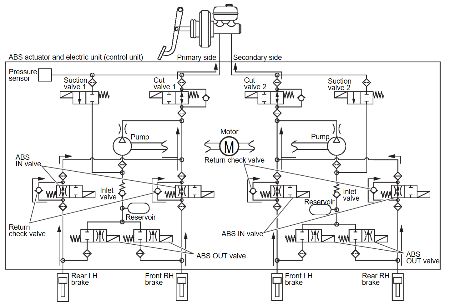
When Brake Release
| Component pars | Not activated | When pressure decrease |
| Cut valve 1 | Power supply is not supplied (open) | Power supply is not supplied (open) |
| Cut valve 2 | Power supply is not supplied (open) | Power supply is not supplied (open) |
| Suction valve 1 | Power supply is not supplied (close) | Power supply is not supplied (close) |
| Suction valve 2 | Power supply is not supplied (close) | Power supply is not supplied (close) |
| ABS IN valve | Power supply is not supplied (open) | Power supply is not supplied (open) |
| ABS OUT valve | Power supply is not supplied (close) | Power supply is not supplied (close) |
| Each brake (fluid pressure) | — | Pressure decreases |
During pressure front RH brake release
- Brake fluid is supplied to the front RH brake through the return check valve of the ABS IN valve and the cut valve 1, and returns to the master cylinder.
During pressure front LH brake release
- Brake fluid is supplied to the front LH brake through the return check valve of the ABS IN valve and the cut valve 2, and returns to the master cylinder.
During pressure rear RH brake release
- Brake fluid is supplied to the rear RH brake through the return check valve of the ABS IN valve and the cut valve 2, and returns to the master cylinder.
During pressure rear LH brake release
- Brake fluid is supplied to the rear LH brake through the return check valve of the ABS IN valve and the cut valve 1, and returns to the master cylinder.
Component Parts and Function
| Component parts | Function |
| Pump |
|
| Motor | Activates the pump according to signals from ABS actuator and electric unit (control unit). |
| Cut valve 1 Cut valve 2 | Shuts off the ordinary brake line from master cylinder. |
| Suction valve 1 Suction valve 2 | Supplies the brake fluid from master cylinder to the pump. |
| ABS IN valve | Switches the fluid pressure line to increase or hold according. |
| ABS OUT valve | Switches the fluid pressure line to increase, hold or decrease according. |
| return check valve | Returns the brake fluid from each brake to master cylinder by bypassing orifice of each valve when brake is released. |
| Reservoir | Temporarily reserves the brake fluid drained from each brake, so that pressure efficiently decreases when decreasing pressure of each brake. |
| Pressure sensor | Detects the brake fluid pressure and transmits signal to ABS actuator and electric unit (control unit). |
CONDITION FOR TURN ON THE WARNING LIGHT
Turns ON when ignition switch ON and turns OFF when the system is normal, for bulb check purposes.
| note | About electric parking brake warning light: Refer to System Description . . |
| Condition (status) | ABS warning light | Brake warning light | ASC warning light |
| Ignition switch OFF (Auto ACC function OFF) | OFF | OFF | OFF |
| For approx. 1 second after the ignition switch is ON | ON | ON | ON |
| Approx. 1 second after ignition switch is ON (when the before engine starts, system is in normal operation) | OFF | ON | OFF |
| After engine starts | OFF | OFF | OFF |
| When brake fluid is less than the specified level (brake fluid level switch ON) | OFF | ON | ON |
| ASC function is malfunctioning | OFF | OFF | ON |
| TCS function is malfunctioning | OFF | OFF | ON |
| ABS function is malfunctioning | ON | OFF | ON |
| EBD function is malfunctioning | ON | ON | ON |
| Brake limited slip differential (BLSD) function is malfunctioning | OFF | OFF | ON |
| Brake assist function is malfunctioning | OFF | OFF | ON |
| Brake force distribution function is malfunctioning | OFF | OFF | ON |
| hill start assist function is malfunctioning | OFF | OFF | ON |
| Brake vacuum sensor function is malfunctioning | OFF | ON | OFF |
| ASC function is operating | OFF | OFF | Blinking |
| TCS function is operating | OFF | OFF | Blinking |
| ABS function is operating | OFF | OFF | OFF |
| EBD function is operating | OFF | OFF | OFF |
| Brake limited slip differential (BLSD) function is operating | OFF | OFF | Blinking |
| Brake assist function is operating | OFF | OFF | OFF |
| Brake force distribution function is operating | OFF | OFF | OFF |
| hill start assist function is operating | OFF | OFF | OFF |
CONDITION FOR TURN ON THE INDICATOR LIGHT
Turns ON when ignition switch turns ON and OFF when the system is normal, for bulb check purposes.
| note | About electric parking brake indicator light: Refer to System Description . . |
| Condition (status) | ASC OFF indicator light |
| Ignition switch OFF (Auto ACC function OFF) | OFF |
| For approx. 1 second after the ignition switch is ON | ON |
| Approx. 1 second after ignition switch is ON (when system is in normal operation) | OFF |
| After engine starts (when system is in normal operation) | OFF |
| ASC setting is OFF (ASC OFF indicator is turn ON) | ON |
| ASC function is malfunctioning | OFF |
| TCS function is malfunctioning | OFF |
![[Previous]](../../../buttons/fprev.png)
![[Next]](../../../buttons/fnext.png)
