Removal and Installation
| warning | Read “General Precautions” when working on the fuel system. Refer to General Precautions . . |
REMOVAL
2WD
| caution | Perform the operation with vehicle on level ground. |
1. Release fuel pressure. Refer to Work ProcedureWork Flow .
.
 .
.2. Open fuel filler lid.
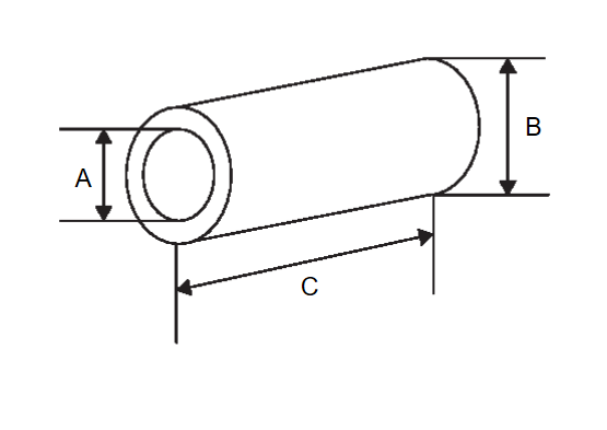
3. Insert a general purpose pipe with the dimensions shown in fuel filler cap less unit and release the pressure inside the fuel tank.
| A | : Over Φ 16 mm (0.63 in) |
| B | : Φ 21.0 mm (0.83 in) |
| C | : 150 mm (5.91 in) |
| note | Insert and hold 80 mm (3.15 in) from the end of the general purpose pipe into the fuel filler port. |
4. Check fuel level on a level ground. If the fuel level is 7/8 of the fuel tank (full or nearly full), draw appropriate amount of fuel from the fuel tank.
| Guideline | : Draw approximately 15 liters (4 US gal, 3-2/8 Imp gal) from a full-tank condition. |
In the event of malfunction in fuel pump, insert a hose measuring 16 mm (0.63 in) in diameter into the filler opening to draw approximately 15 liters (4 US gal, 3-2/8 Imp gal) fuel.
5. Remove second seat.
6. Remove inspection hole cover.
- Using a screwdriver, remove it by turning clips clockwise by 90 degrees.
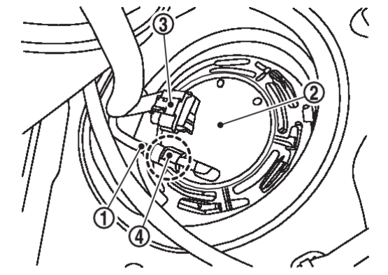
7. Disconnect harness connector  and quick connector
  .
.
 and quick connector
  .
. | : Fuel feed tube |
 | : Fuel level sensor unit, fuel filter and fuel pump assembly |
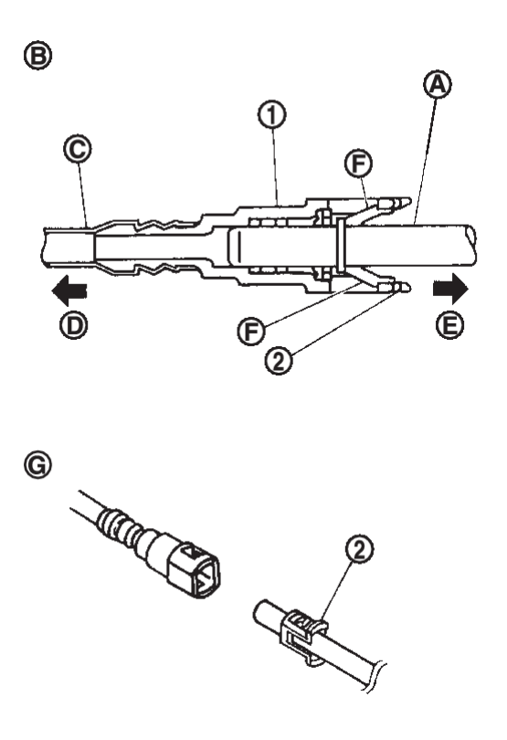
Disconnect quick connector as follows:
- Hold the sides of connector, push in tabs
 and pull out fuel feed tube.
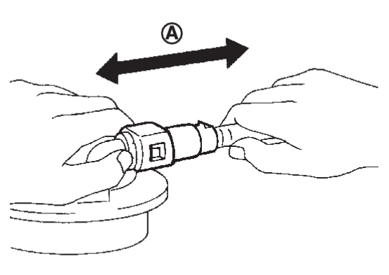
: Pull - If quick connector sticks to tube of fuel level sensor unit, fuel filter and fuel pump assembly, push and pull quick connector several times until they start to move. Then disconnect them by pulling.
| caution |
|
8. Remove lock ring according to the following instructions:
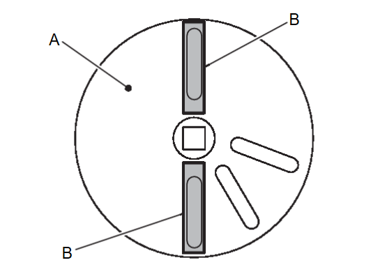
(1) Install pawl (B) of unified fuel lock ring wrench [SST: KV101207S0 ( — )] (A) to the position shown in the figure.
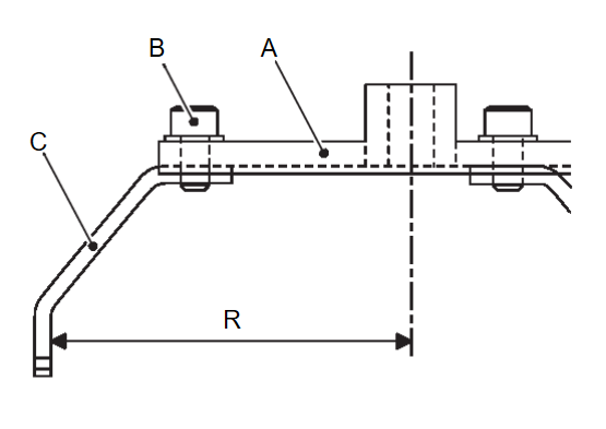
(2) Temporarily tighten mounting bolt (B) of the pawl according to the measurement (R) from the center of unified fuel lock ring wrench [SST: KV101207S0 ( — )] (A) to the end of pawl (C).
| R | : 82 mm (3.23 in) |
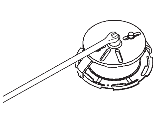
(3) Set unified fuel lock ring wrench [SST: KV101207S0 ( — )] to lock ring and tighten the mounting bolt of the pawl.
9. Remove fuel level sensor unit, fuel filter and fuel pump assembly.
AWD
| caution | Perform the operation with vehicle on level ground. |
1. Release fuel pressure. Refer to Work ProcedureWork Flow .
.
 .
.2. Open fuel filler lid.
3. Insert a general purpose pipe with the dimensions shown in fuel filler cap less unit and release the pressure inside the fuel tank.
| A | : Over Φ 16 mm (0.63 in) |
| B | : Φ 21.0 mm (0.83 in) |
| C | : 150 mm (5.91 in) |
| note | Insert and hold 80 mm (3.15 in) from the end of the general purpose pipe into the fuel filler port. |
4. Check fuel level on a level ground. If the fuel level is 7/8 of the fuel tank (full or nearly full), draw appropriate amount of fuel from the fuel tank.
| Guideline | : Draw approximately 15 liters (4 US gal, 3-2/8 Imp gal) from a full-tank condition. |
In the event of malfunction in fuel pump, insert a hose measuring 16 mm (0.63 in) in diameter into the filler opening to draw approximately 15 liters (4 US gal, 3-2/8 Imp gal) fuel.
5. Remove second seat.
6. Remove inspection hole cover.
- Using a screwdriver, remove it by turning clips clockwise by 90 degrees.
7. Disconnect harness connector  and quick connector
  .
.
 and quick connector
  .
. | : Fuel feed tube |
 | : Fuel level sensor unit, fuel filter and fuel pump assembly |
Disconnect quick connector as follows:
- Hold the sides of connector, push in tabs
 and pull out fuel feed tube.
: Pull - If quick connector sticks to tube of fuel level sensor unit, fuel filter and fuel pump assembly, push and pull quick connector several times until they start to move. Then disconnect them by pulling.
| caution |
|
8. Remove lock ring according to the following instructions:
(1) Install pawl (B) of unified fuel lock ring wrench [SST: KV101207S0 ( — )] (A) to the position shown in the figure.
(2) Temporarily tighten mounting bolt (B) of the pawl according to the measurement (R) from the center of unified fuel lock ring wrench [SST: KV101207S0 ( — )] (A) to the end of pawl (C).
| R | : 82 mm (3.23 in) |
(3) Set unified fuel lock ring wrench [SST: KV101207S0 ( — )] to lock ring and tighten the mounting bolt of the pawl.
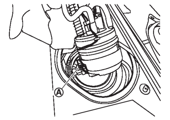
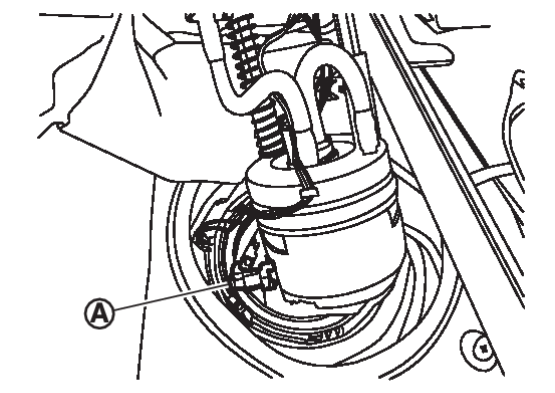
9. Raise fuel level sensor unit, fuel filter and fuel pump assembly.
| caution |
|
10. Separate fuel tube as per the following steps to remove fuel level sensor unit, fuel filter and fuel pump assembly.
- Disconnect harness connector
 .
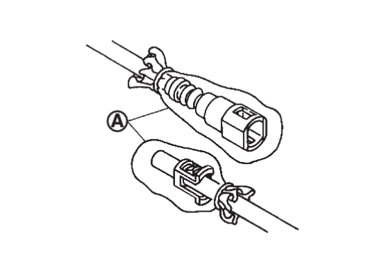
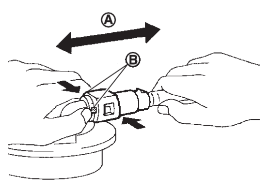
. - Pinch quick connector
 square-part with your fingers, and pull out the quick connector by hand.
 - If quick connector and tube on sender unit are stuck, push several times until they move, and pull out.
note When separating the fuel tube, tie a gasoline-resistance rope to the tip of the fuel tube and leave the rope on the fuel tank side to easily pull the fuel tube for installation.
Sub Fuel Level Sensor Assembly
1. Remove fuel level sensor unit, fuel filter and fuel pump assembly.
2. Remove lock ring according to the following instructions:
(1) Install pawl (B) of unified fuel lock ring wrench [SST: KV101207S0 ( — )] (A) to the position shown in the figure.
(2) Temporarily tighten mounting bolt (B) of the pawl according to the measurement (R) from the center of unified fuel lock ring wrench [SST: KV101207S0 ( — )] (A) to the end of pawl (C).
| R | : 82 mm (3.23 in) |
(3) Set unified fuel lock ring wrench [SST: KV101207S0 ( — )] to lock ring and tighten the mounting bolt of the pawl.
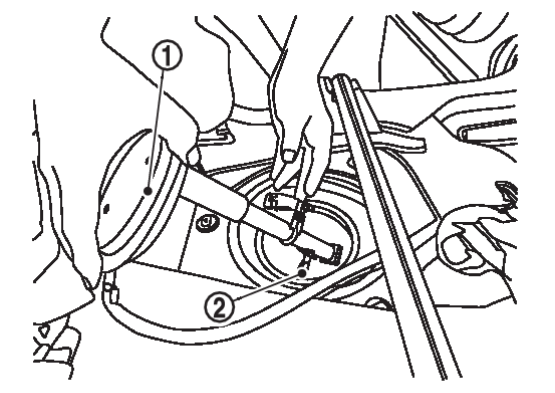
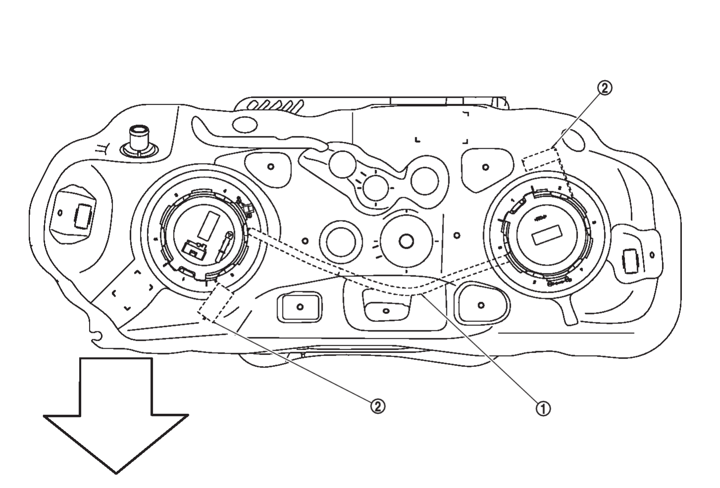
3. Remove sub fuel level sensor assembly  .
.
 .
.| caution |
|
| note | Tie a gasoline-resistance rope to a tip of the tube. Draw and leave the rope to the fuel tank side so that the rope can be the guide for installation. |
INSTALLATION
2WD
Note to the following, and install in the reverse order of removal.
Fuel Level Sensor Unit, Fuel Filter and Fuel Pump Assembly
1. Install new O-ring to fuel tank without any twist.
| caution | Do not reuse O-rings. |
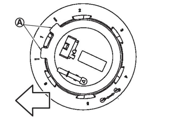
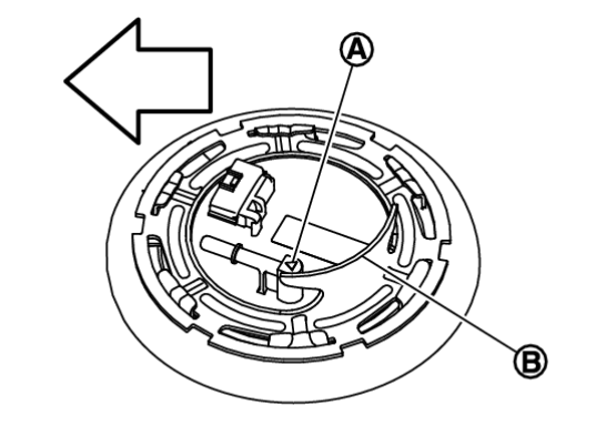
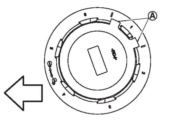
2. Install the fuel level sensor unit, fuel filter and fuel pump assembly on the fuel tank with the fuel level sensor unit, fuel filter and fuel pump assembly face  faced the shown in the figure against the arrow vehicle front.
 faced the shown in the figure against the arrow vehicle front.
 | : Vehicle front |
| caution |
|
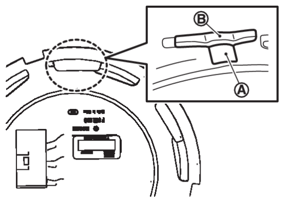
3. Install it so that the guard part  of the lock ring is at the position shown in the figure with respect to the fuel pump pipe part
  .
.
 of the lock ring is at the position shown in the figure with respect to the fuel pump pipe part
  .
.  | : Vehicle front |
4. Install lock ring for fuel level sensor unit, fuel filter and fuel pump assembly with unified fuel lock ring wrench [SST: KV101207S0] ( — ) by turning clockwise.
| caution |
5. Connect quick connector of fuel feed tube as per following procedures.
(1) Check the connection for damage or any foreign materials.
(2) Align the connector with the tube, then insert the connector straight into the tube until a “click” sound is heard.
6. Connect harness connector.
Inspection Hole Cover
- Before installing inspection hole cover, check that the connecting part has no fuel leakage. Refer to InspectionInspection

1. Install inspection hole covers with the front mark (arrow) facing front of vehicle.
2. Lock clips by turning counterclockwise.
AWD
Note to the following, and install in the reverse order of removal.
Sub Fuel Level Sensor Assembly
1. Install new O-ring to fuel tank without any twist.
| caution | Do not reuse O-rings. |
2. Using the rope left on the fuel tank side at removal, run the fuel tube inside the fuel tank to install the sub fuel level sensor assembly to the fuel tank.
| caution |
3. Install the sub fuel level sensor assembly on the fuel tank with the fuel level sensor unit, fuel filter and fuel pump assembly face  faced the shown in the figure against the arrow vehicle front.
 faced the shown in the figure against the arrow vehicle front.
 | : Vehicle front |
| caution |
|
Fuel Level Sensor Unit, Fuel Filter and Fuel Pump Assembly
1. Install new O-ring to fuel tank without any twist.
| caution | Do not reuse O-rings. |
2. Connect the fuel tube as per the following steps.
4. Install the fuel level sensor unit, fuel filter and fuel pump assembly on the fuel tank with the fuel level sensor unit, fuel filter and fuel pump assembly face  faced the shown in the figure against the arrow vehicle front.
 faced the shown in the figure against the arrow vehicle front.
 | : Vehicle front |
| caution |
5. Install it so that the guard part  of the lock ring is at the position shown in the figure with respect to the fuel pump pipe part
  .
.
 of the lock ring is at the position shown in the figure with respect to the fuel pump pipe part
  .
.  | : Vehicle front |
6. Install lock ring for fuel level sensor unit, fuel filter and fuel pump assembly with unified fuel lock ring wrench [SST: KV101207S0] ( — ) by turning clockwise.
| caution |
7. Connect quick connector of fuel feed tube as per following procedures.
(1) Check the connection for damage or any foreign materials.
(2) Align the connector with the tube, then insert the connector straight into the tube until a “click” sound is heard.
8. Connect harness connector.
Inspection Hole Cover
- Before installing inspection hole cover, check that the connecting part has no fuel leakage. Refer to InspectionInspection

1. Install inspection hole covers with the front mark (arrow) facing front of vehicle.
2. Lock clips by turning counterclockwise.
![[Previous]](../../../buttons/fprev.png)
![[Next]](../../../buttons/fnext.png)
 are completely depressed. Never twist it more than necessary.


 away from heat. Be especially careful when welding near the resin tube.